5AR4/GZ34 it is! 🙂
Remember that the 5V winding on the 302AX is 5V@3A, using a 2A rectifier will result in high heater voltage, .22-.47 ohm resistor in series will drop the voltage roughly .5v-1v. This will help extend the life of the 5AR4. You won't know until you have it all breadboarded, hooked up and running. Then when it's good and warmed up monitor both primary (mains) voltage and secondary voltage. This is worth the time, I know most hobbyist's just want to fire it up after soldering and be done. But dialing in the smallest of details will help the longevity of precious devices. Anyway back to the test. When monitoring your amp note a high and low on the primary also note the high and low on the secondary at the same time. You will see something like at 125vac on primary you get 5.9v on the secondary, with a low of 115vac on the primary you get 5.4v on the secondary. You know you can safely drop .5v. Why? You don't want to run the rectifier tube too low, a little high isn't terrible but in my opinion when you run modern 5AR4's at 6V on the heater they don't last very long.
If you do use a dropping resistor get at least 5 watters.
I run a 3A rectifier on my Hammond and with primary at 115 I am still a C hair over 5v.
Last edited:
Procedure
Hi FMB,
That bring up an item I have been pondering. Do I first assemble the individual sections. Each 1 at a time starting with the PS then adding the driver stage, etc.
In a temporary fashion using barrier strips, european type, breadboard or whatever and test all assemblies before I solder this together? Like a prototype assembly. Or does one just solder it all together, test, unsolder, replace to tune etc...?
I would think with the depth of analysis that is going on here that the prototype assembly is what we are doing but you'll have to tell me
Thanks!
Ron, the solder sucker hater
DMM
Hi FMB,
Please direct me to the subject item that has the proper scales to obtain accurate C hair measurements, Fluke?
Thanks!
Ron
Hi FMB,
Please direct me to the subject item that has the proper scales to obtain accurate C hair measurements, Fluke?
Thanks!
Ron
Prototype
Hi,
I mean are we going to construct a test assembly?
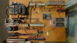
I did so in the past as photo shown, very useful in what I was doing . If so I will
start making make a tube sort of one now as we decide the final circuit.
Sort of like what Tubelab has on one of his pages.
thanks!
Ron
Hi,
I mean are we going to construct a test assembly?
I did so in the past as photo shown, very useful in what I was doing . If so I will
start making make a tube sort of one now as we decide the final circuit.
Sort of like what Tubelab has on one of his pages.
thanks!
Ron
Attachments
Member
Joined 2009
Paid Member
A mock up first will allow you to confirm you're happy and try some tweaks or different driver tubes - just keep it safe.
Hi FMB,
That bring up an item I have been pondering. Do I first assemble the individual sections. Each 1 at a time starting with the PS then adding the driver stage, etc.
In a temporary fashion using barrier strips, european type, breadboard or whatever and test all assemblies before I solder this together? Like a prototype assembly. Or does one just solder it all together, test, unsolder, replace to tune etc...?
I would think with the depth of analysis that is going on here that the prototype assembly is what we are doing but you'll have to tell me
Thanks!
Ron, the solder sucker hater
If I were you I would probably mock up the power supply (safely). This would include running the heater wires to the tube sockets. You want the tubes to load down the heater/filament taps and use a resistive load for the B+.
2 Pcs Green 50W Watt 5K Ohm 5% Aluminum Shell Wire Wound Resistors - Newegg.com
Something like this to load down each channel's PS rail.
After the power supply is built and the numbers all fall in line then you can work on adding the actual circuit.
Please direct me to the subject item that has the proper scales to obtain accurate C hair measurements
A Start
Hi All,
Ok, so now I will build a mockup, and look for a C-h scale.You all are too much!
Thanks,,
Ron
Hi All,
Ok, so now I will build a mockup, and look for a C-h scale.You all are too much!
Thanks,,
Ron
Hello All,
After reading all of your fine efforts and concerns in what I think with my limited knowledge of the discussion I would like to go with the 5AR4 for the PS.
I am really appreciative of the depth that you all have presented. I hope I am making the right decision. I read this ---
powersupplies
several times with great interest. I wonder really how much is reality in the implementation with regards to the sound produced. I don't posses the knowledge base to properly evaluate, It may be one of those "how many angels can fit on the head of a pin" things. I do know that the best, smoothest, stable, current we can supply will give us an outstanding start. So any way that my vote.
What say you?
And really thanks!
Ron
that is subjective...my 5894 SET was chosen over the 2A3 amp that i also built.....he said that while the 2A3 sounded crystal clear, the 5894 had more in terms of emotions with sounds....how about that...?😱
Member
Joined 2009
Paid Member
[IMG said:https://www.performanceboats.com/attachment.php?attachmentid=44597&stc=1&d=1244670198[/IMG]
so 35 CH per in = 21 AWG. Too Scary!😱
But if you don't need the gain ? and if you have enough B+ headroom I wonder why not use a high quality resistor. It may be old fashioned but it's simple, reliable and can sound wonderful. Mr. Ciuffoli has built more tube amps than I'll ever hear - he tried a CCS loaded triode-wired D3a driving a 2A3 and preferred the result with a resistor plate load instead.New 2A3
Attachments

Member
Joined 2009
Paid Member
I would propose the next step is to get the experimental chasis under construction - there's a time for chit chat and a time for action, it's time to get hands dirty. There can be a lot of fun in trying things out, collectively we should recommend some options so that the parts can be ordered. I would propose trying 2 or 3 different driver tubes and to allow easy comparison you may like to have 2 or 3 sockets wired up so you can swap between them easily for listening tests. You'll want a selection of resistor values to go with. You'll want a selection of bypass and coupling caps too - I have noticed sound changes between Russion PIO and MKP film types - see which you like.
Yes if you want to play around with different drivers you can adjust the 2k7 resistor depending on current draw and operating point. I still really like the 6N7. And then there are the triode strapped high gm pentodes like the 12HL7 or D3a.
On It
Hi,
Hobbyists my a$$, you all are electrical engineers!
I had Dr. Stuff today. Gonna go into the plant tomorrow and get moving on the mockup. Since I have decided to construct a stero unit, of the dimensions width 17, depth 12. I will cut the material tomorrow. Now what should that be, cold rolled steel, stainless steel, non-magnetic stainless, or the bauxite alloy that the final product will be? Let me know.
Thanks!
Ron
Observation
Hi,
And another thing, I belong to 2 other "forums". Lateral-G (cars), and the Powerbasic fourm. And by FAR and a country mile, you folks, at least you few, are the most patient, considerate, and helpful batch of people I have ever encountered over the wire. And I am truly greatful to you few and will someday show it. It is a rare thing to find in person, let alone in such a circumstance as this. I will certainly do my best to honour your helpful nature in the final product.
As one of you referenced " once in a lifetime ".
regards,
Ron
Material
Hi,
I checked some tube chassis that I have
Cary V12-magnetic steel, Bellari phono preamp-magnetic steel, Dared M5-P- non magnetic stainless, Antique Sound Lab 300b-non magnetic stainless steel, Williamson 6550- magnetic steel. Now interestingly enough the only units that have any floor noise at all, are the 2 commercial products made from stainless steel. The Dared and the ASL 300b. But maybe that's old news to you guys.
Thoughts....
Ron
Ron,
Go with aluminum alloy of decent thickness. 17 X 12 (inches) for the top surface area is fine. Leave yourself plenty of room in the height dept., at least 4 inches. It's the old story of better to be looking at it than needing and not having it.
You can buy or recycle a sturdy piece of plywood for use as a "breadboard". Clip leads are used to connect things to each other. "Breadboarding" allows for easy try this and try that, before committing to something specific. FWIW, "breadboarding" is easy with Octal small signal tubes, courtesy of relay sockets.
BTW, most of us are enthusiasts, not professionals. I'm an IBM mainframe CICS system programmer. Any number of occupations are represented here.
Member
Joined 2009
Paid Member
at least you few, are the most patient
The truth is, DIY audio is an addiction and this forum is really a therapy group ��
I've done my prototyping using an aluminium chases, 17" wide by 8" (or so) and 3" deep. I haven't tried a wooden breadboard. I like the Aluminium chases as a prototype platform because it's metal and that means I can earth it and operate it more safely than an open system. I also get to drill holes and stuff like that !
The truth is, DIY audio is an addiction and this forum is really a therapy group
Hello my name is Jason and I build myself amps when I already have amps. Help I can't stop this terrible affliction 😉
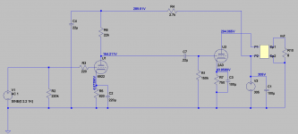
Also I forgot to mention you can fine tune the B+ voltage by adjusting the first cap 2.2uF. I crunched the numbers and simmed everything too so it should be accurate. If you can swing it I would try and get a NOS Mullard GZ34, they are expensive but they are bulletproof.
I use plywood to screw everything down for breadboarding. Honestly I don't have hum issues this way as long as you watch your signal currents and power supply currents a d don't mix them up. The breadboarding is the only way to test driver sonics with your own ears. It took me a year to find a driver for my latest build, I settled on a CCS loaded 6N7. It's a great performer! I will post the schematic for the 6SN7 version if you are still interested in that option.
and i have ten tube amps projects in various stages of completion...just can't have enough, i am addicted....😀
- Status
- Not open for further replies.
- Home
- Amplifiers
- Tubes / Valves
- 2A3 driver