Ron,
If you decide to SS rectify the B+, use 2X of this part. Insert a CL-90 inrush current limiting thermistor in the line between the diode cathodes and the 1st filter capacitor. The negative temperature coefficient (NTC) thermistor will slightly delay B+ rise and keep the power trafo from clanging, should you choose to use a large valued cap. in the 1st position of the PSU filter.
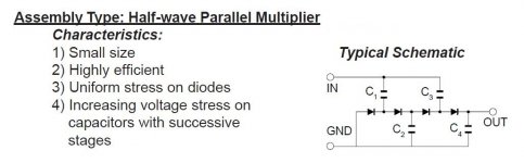
To provide max. protection to the costly EML 2A3s, go the "fixed" bias route. An instant on, SS rectified, bias supply electrostatically shields the filament from the positive potential on the plate and allows emission to safely begin. Instead of using the tap, voltage multiply the 5 VAC winding to derive the bias supply. The uploaded schematic is for a positive rail. So, "stand" everything on its head. Noise free Schottky diodes are your "friend" in the multiplier too.
If you decide to SS rectify the B+, use 2X of this part. Insert a CL-90 inrush current limiting thermistor in the line between the diode cathodes and the 1st filter capacitor. The negative temperature coefficient (NTC) thermistor will slightly delay B+ rise and keep the power trafo from clanging, should you choose to use a large valued cap. in the 1st position of the PSU filter.
To provide max. protection to the costly EML 2A3s, go the "fixed" bias route. An instant on, SS rectified, bias supply electrostatically shields the filament from the positive potential on the plate and allows emission to safely begin. Instead of using the tap, voltage multiply the 5 VAC winding to derive the bias supply. The uploaded schematic is for a positive rail. So, "stand" everything on its head. Noise free Schottky diodes are your "friend" in the multiplier too.
Attachments
On the other hand if something goes wrong with the bias supply and you go into thermal runaway..........
Bridge rectification limits max DC current output to something like .62*ACmaxcurrent. So .230*.62=.14 or 140mA. If you choose SS use a full wave w/CT.
Bridge rectification limits max DC current output to something like .62*ACmaxcurrent. So .230*.62=.14 or 140mA. If you choose SS use a full wave w/CT.
Member
Joined 2009
Paid Member
To provide max. protection to the costly EML 2A3s, go the "fixed" bias route.
I've never heard of 2A3's getting hurt due to start-up stresses, would like to learn more about this...
For the auto-bias version, when the B+ comes up quickly there will be several hundred volts on the plate, the grid and filament will be at ground potential. But the filament is cold so no current will flow.
The filament will then warm up and current will start to flow. There will be a bit of a rush in order to charge up the filament bypass capacitor, but this is self-limiting as the filament voltage rises to roughly 45V. Why is this too much stress?
I like auto-bias, set and forget.
The Hammond power trafo the OP already possesses is configured for FWCT. Bridge rectification is out.
Size the wattage of the 10 Ω bias set resistors so that if a tube goes into thermal runaway the resistor, not the tube, goes up in smoke.
Another option, perhaps the "ultimate", is combination bias. Use a 100 Ω resistor bypassed by a 470 μF. cap. to provide part of the total 2A3 bias and a convenient test point. A negative rail provides the remainder of the total bias. If the bias supply fails, the self bias network protects the tube. Here too, the resistor can do double duty as a fuse.
Last edited:
I've never heard of 2A3's getting hurt due to start-up stresses, would like to learn more about this.
It's my "belt and suspenders" mindset. You are probably correct about it being overkill, but ... The OP has hideously expensive EML 2A3s. I want 100% to eliminate the possibility of cathode stripping. A 5AR4 does that, automatically. OTOH, SS diodes are instant on. A NTC thermistor provides a slight delay, which combined with an instant on C- supply, disposes of the matter.
Member
Joined 2009
Paid Member
I have 0.00001% of your experience but I'd be brave enough to call you out on that one - I think there's negligible risk of cathode stripping on a 2A3 in the circuit we're considering and I'd not want the complexity of fixed or combination bias - there's perhaps more risk of a bias error than cathode stripping with this approach.
If we're going to be risk adverse - keep the circuit simple (proven concepts, less error prone construction, fewer parts to fail etc. etc.) and 'invest' in a 'cheap' pair of 2A3's that can be used to validate the circuit, let it burn in, stress it a little to weed out a bad part or connection before the fancy tubes are used.
If we're going to be risk adverse - keep the circuit simple (proven concepts, less error prone construction, fewer parts to fail etc. etc.) and 'invest' in a 'cheap' pair of 2A3's that can be used to validate the circuit, let it burn in, stress it a little to weed out a bad part or connection before the fancy tubes are used.
Last edited:
Member
Joined 2009
Paid Member
I believe Ron wants to use cascading 6SN7's, he already has an amp with similar topology and he really likes it. I personally like two stage designs myself.
I don't like the multiple stage approach - although I have NOT HEARD a comparison myself, so my objections are purely theoretical and I am open to learning from those who have more experience.
I don't like the additional complexity of two stages, not so easy to voice the amplifier, more parts to play with to get the sound right, more operating points to get right. The 6SN7 is not as linear as folklore makes out based on the reading I've done and a cascade tends to add greatly to the complexity of the harmonic profile of the amplifier - not necessarily to the better. Two 6SN7's gives you too much gain unless you 'cripple' one stage somehow.
I say 'so what' if the OP heard a completely different amplifier and liked it - it's a 300B amp, different power supply, output tube, output transformer etc. etc. I've heard SS amps I like the sound of too - it's irrelevant 😉
A single stage driver has much to commend it. Triode-wired pentodes can be very linear indeed, offer a good combination of gain and plate resistance for driving a 2A3 and makes for a design with fewer parts and less unintended consequences as a result.
Chinese 2A3s are about 40 bucks each. That's not inexpensive. Do the initial "breadboarding" with triode wired 6AV5s. They are about $4 each. 😀 Darned tootin', I'm a cheapskate. 
Member
Joined 2009
Paid Member
I'm a cheapskate.
I'm not touching that one 😀
...Still, I'd go with the $40 2A3's - that way you can be sure to test out everything, including filament heater, tube socket wiring etc. etc.
Not quite a single small signal stage, but very much in the same spirit is a constant current source (CCS) loaded 6922 section DC coupled to an IRFBC20 source follower. More than enough gain to drive a 2A3 into clipping, when the setup is fed with the full 2 VRMS O/P of a "standard" CDP. Deal with any non-linearity in the voltage gain block by omitting a cathode resistor bypass capacitor. CCS loading ensures the "full" μ of the triode is obtained. A simple 10M45S might be good enough as the CCS, here.
We are spinning our tires here.
Seriously worried about cathode bias with the 2A3 but you want to draw grid current? If you don't want to draw grid current what is the point of the source follower?
I feel he has a perfect power transformer with all the taps he needs to make a nice 2A3 amplifier. I agree with Bigun in that it's probably safest to run those 2A3's cathode biased, bypassed with a suitable filter to ensure adequate low end response, 100uF should be good with a 750 ohm cathode resistor. Simple, elegant, and proven design that works great.
Yes get spare inexpensive 2A3's for testing and backups.
I too vote for a single stage but I have breadboarded a cascaded 6SN7 to drive my 6HJ5 amp and it didn't sound at all bad, it was too sensitive for me, I didn't need all that gain. I did end up using a single stage to drive the 6HJ5, a CCS (10M45S) loaded 6N7, mu=35. Works great with all my modern sources, I think I got around 15db gain.
I also vote for tube rectifier. Either modern 5AR4 with serial diodes or I like the 5U4GB.
Running with Eli's idea of using a CCS loaded 6922. I use the 10M45S point to point without any issues. The driver has low rp and high gm, plenty of current.
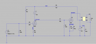
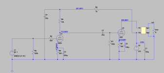
Rough schematic of simulations so far. I also have the simulations for the cascaded 6SN7 approach. I like the idea of one stage driving the 2A3 for a two stage amp.
Rough schematic of simulations so far. I also have the simulations for the cascaded 6SN7 approach. I like the idea of one stage driving the 2A3 for a two stage amp.
Attachments
Member
Joined 2009
Paid Member
The CCS load brings the obvious advantage of a horizontal load line for the driver, which means you realize the maximum gain. If going the sand route, I'd look at the Wavebourn Gyrator as being a better option. But if you don't need the gain ? and if you have enough B+ headroom I wonder why not use a high quality resistor. It may be old fashioned but it's simple, reliable and can sound wonderful. Mr. Ciuffoli has built more tube amps than I'll ever hear - he tried a CCS loaded triode-wired D3a driving a 2A3 and preferred the result with a resistor plate load instead.http://www.audiodesignguide.com/New2A3/new2A3.html
Ron will need a source that puts out 2Vrms or a preamp to get max output with this configuration. I don't have much experience for designing around the 6922 so if anyone has any better operating points let me know. Gain is 10db. 2% THD @ 3 watts out.
Attachments
Last edited:
Member
Joined 2009
Paid Member
That's probably fine for a modern CD player, but might be too low otherwise, depending on what source Ron plans to use. The grid of a 2a3 doesn't need gobs of current, a higher plate load resistor and lower anode current through the driver maybe?
Last edited:
my rule of dumb......if the 2A3 grid is biased -45volts, then for an input sensitivity of
say 1 volt peak, then the drive stage should have a gain of 45/1 or x 45...
my other rule of dumb....plate voltage of driver stage to be 3 x 45 plus 50 volts...or at least 185 volts, more is better...
say 1 volt peak, then the drive stage should have a gain of 45/1 or x 45...
my other rule of dumb....plate voltage of driver stage to be 3 x 45 plus 50 volts...or at least 185 volts, more is better...
Preamp
Hi,
Yes I plan on using this amp with a preamp.
Do I need to measure something on the targt unit?
I'll put several 2a3 (dual source) on the buy list for the burn in and testing.
Wish I could take you 3 out for a drink!
FMB, Bigun,Eli. I really have the right team here!
Would it not just be easier to completely remove the possibility of cathode stripping by using one of those delay relays previously shown in this thread?
Thoughts?
Ron
Member
Joined 2009
Paid Member
If you use a tube rectifier then you'll have a slower B+ rise. Did you decide if it will be tube or SS rectifier ?
Delaying the B+ until after the 2a3 filament is hot guarantees a sudden current pulse through the tube when the B+ hits. I'm not sure that's desirable either.
If you believe cathode stripping is a real risk you might need something more sophisticated.
In my view, there's more stress on the tube from inrush current to the filament when it gets heated up at turn on, some folk put a thermistor in series with the primary of the power transformer - there are innexpensive slow start modules available from ebay that use thermistors on the mains AC to limit start up current and then close a relay across the thermistor after a delay.
Rectifier
Hello All,
After reading all of your fine efforts and concerns in what I think with my limited knowledge of the discussion I would like to go with the 5AR4 for the PS.
I am really appreciative of the depth that you all have presented. I hope I am making the right decision. I read this ---
powersupplies
several times with great interest. I wonder really how much is reality in the implementation with regards to the sound produced. I don't posses the knowledge base to properly evaluate, It may be one of those "how many angels can fit on the head of a pin" things. I do know that the best, smoothest, stable, current we can supply will give us an outstanding start. So any way that my vote.
What say you?
And really thanks!
Ron
I like GZ34s and 5AU4/5V3s as well as,"wait for it"
Schottky/Cree diodes. They are dead quiet,soft turn-on,extremely linear,and they sound much like a vacuum tube rectifier but without losses.
Schottky/Cree diodes. They are dead quiet,soft turn-on,extremely linear,and they sound much like a vacuum tube rectifier but without losses.
- Status
- Not open for further replies.
- Home
- Amplifiers
- Tubes / Valves
- 2A3 driver