Hi, http://www.lundahl.se/wp-content/uploads/datasheets/1620_3_7_9202.pdf
On page two there is an example of: 90mA DC current, Rsource=650 and Rload=8, 7Hz-25kHz Your 2A3 will have slightly higher source resistance but should should still have great low end response. High frequency looks good but they do not state at which power level they took these measurements.
http://www.lundahl.se/wp-content/uploads/datasheets/1664.pdf
The LL1664 says at 50mA it's primary inductance is 35H, expect it to be slightly lower at 60mA, probably around 30H, plenty for a 2A3.
I have no real world experience with these type of transformers so maybe someone that has used them can jump in and give their opinion. Myself I would probably go with the 1664AM.
DCR
Hi FMB,
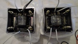
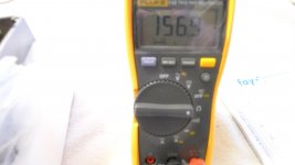
You asked me to measure the DCR of the OPTs.
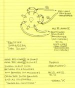
As pictured in the photo there are 4 wires coming from each one.
2 wires are what we will call the upper ones and 2 wires the lower ones.
The resistance was measured across the upper and lower pairs.
Left upper = 1.3, Left lower = 164.7
Right upper = 1.2, Right lower = 156.9
So its Greek to me but there you go for the simulation.
thanks a bunch!
Ron
Hi FMB,
You asked me to measure the DCR of the OPTs.
As pictured in the photo there are 4 wires coming from each one.
2 wires are what we will call the upper ones and 2 wires the lower ones.
The resistance was measured across the upper and lower pairs.
Left upper = 1.3, Left lower = 164.7
Right upper = 1.2, Right lower = 156.9
So its Greek to me but there you go for the simulation.
thanks a bunch!
Ron
Attachments
Hi, http://www.lundahl.se/wp-content/uploads/datasheets/1620_3_7_9202.pdf
On page two there is an example of: 90mA DC current, Rsource=650 and Rload=8, 7Hz-25kHz Your 2A3 will have slightly higher source resistance but should should still have great low end response. High frequency looks good but they do not state at which power level they took these measurements.
http://www.lundahl.se/wp-content/uploads/datasheets/1664.pdf
The LL1664 says at 50mA it's primary inductance is 35H, expect it to be slightly lower at 60mA, probably around 30H, plenty for a 2A3.
I have no real world experience with these type of transformers so maybe someone that has used them can jump in and give their opinion. Myself I would probably go with the 1664AM.
The OP already has O/P "iron" in his possession, that were gifts from his children.
Last edited:
Hi Eli,
How you been? Do you mean this one?
http://www.hagtech.com/pdf/clarionarticle.pdf
Thanks!
Ron
The "Level 5" on page 3 of this thread shows generally how to set up a 5AR4 rectified PSU. I would not necessarily use the parts values shown.
Member
Joined 2009
Paid Member
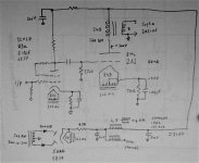
Here's a sketch of what I had in my head based on the thread so far.
With the standard -45V grid-cathode bias of the 2A3 and an operating point of 250V plate-cathode at 60mA you'll need a cathode bias resistor of 750R and you'll want 295V on the plate. With a nominal 10V drop across the DCR of the OPT you'll want 305V on the B+ supply (I suggested 310V in my sketch).
Your power transformer has 300-0-300 windings at > 200mA so in normal operation you'll see a bit more than this as you won't be drawing the nominal design current but once rectified you'll lose voltage through the tube rectifier (perhaps 12V with a 5AR4) and you'll lose voltage through the choke filter. I prefer a choke input filter after a tube rectifier but this won't get you to the B+ you want. So, perhaps you'll want to consider a small cap after the tube rectifier which will elevate the voltage and a series resistor to reduce the stress on the rectifier.
The first cap in the power supply, after the rectifier, has to be adjusted to get the voltage you want WHEN the amplifier is warm and drawing the correct idle current. I've not used this trick - there maybe reasons why it is to be avoided.
I've sketched the use of a single input / voltage amplifier tube, with a few options listed out. The idea is to connect the input tube screen grid to the plate, this linearizes the tube and reduces it's output impedance - some folk refer to it as 'triode wired'.
Attachments
Looks good Bigun! Yes 750R for the cathode resistor | | 100uF. I would lower the grid resistance below 200k, especially with a low rp driver. I believe Ron wants to use cascading 6SN7's, he already has an amp with similar topology and he really likes it. I personally like two stage designs myself. The schematic he likes is posted somewhere in this thread, I will repost it here. I am still working on some revisions for people to look over. The sensitivity is high, 34db gain I believe. You can drop the gain down to 26db by dropping the first stage cathode bypass cap. I would leave the second 6SN7 triode's cathode bypass cap in there to keep the rp low to drive the 2A3, that value cap is 220uF and can be lowered to 33uF without any loss of low end response. The first coupling cap can be reduced to .1uF. Current draw per 6SN7 triode is 2.5mA, so 5mA per bottle. That's 65mA per channel or 130mA total. The values for the power supply can be realized as soon as which rectifier is chosen.
I am not a fan of using SS diodes in series with VR tube plates, if you want SS rectification then just use SS rectification and don't waste a tube.
The Hammond power transformer has 110v and 100v primary taps so in theory he can get the HT secondary up to 360vac.
Personally I think the 5U4GB is a tougher tube and will handle the repetitive peak forward current better than the 5AR4. You will get more of a voltage drop across it but that can be made up elsewhere, like with a large C input (50uF) or using the other primary taps etc......I also only like to use 1 choke so I share a choke between channels and then branch off after via RC filters. The 5U4GB's higher ratings allow the use of more capacitance which gives better filtering. If you use the 5AR4 use less capacitance and more chokes, pick your poison. Good 5U4GB's can be had for cheap where as good vintage 5AR4's cost a fortune these days, I know I just sold some out of my stash, I built an entire guitar amp for the price of two Mullard GZ34's I sold.
Attachments
Yes indeed, desirable OS 5AR4/GZ34s are outrageously expensive. The matter is dealt with by using the inexpensive, current production, Sovtek 5AR4 and the installation of the series SS diode tweak. The SS diodes shore up the Saratov, Russia, made tube in the area of voltage handling, where it has some trouble. Sonics and current handling of the New Sensor product are completely satisfactory. FWIW, I suggest the UF4007, instead of the 1N4007, on the hypothesis that less switching noise, from the very beginning, should be better. However, it must be stated that the vacuum diodes block SS diode switching noise from entering the B+ rail. I worry, perhaps needlessly, about noise getting into the power trafo.
Both the 5U4GB and 5AR4/GZ34 are rated for a 250 mA. B+ draw. The 5AR4 is rated for a bigger filter cap. than the 5U4GB. The 5AR4 draws 2 A. of heater current, while the 5U4GB draws 3 A. While those points favor the 5AR4, they are not particularly significant. What is significant is that the cathode sleeve in a 5AR4 slows B+ rise and provides a degree of protection for the signal tubes. Those EML 2A3s are very costly and can use all the protection that can be provided.
Both the 5U4GB and 5AR4/GZ34 are rated for a 250 mA. B+ draw. The 5AR4 is rated for a bigger filter cap. than the 5U4GB. The 5AR4 draws 2 A. of heater current, while the 5U4GB draws 3 A. While those points favor the 5AR4, they are not particularly significant. What is significant is that the cathode sleeve in a 5AR4 slows B+ rise and provides a degree of protection for the signal tubes. Those EML 2A3s are very costly and can use all the protection that can be provided.
Attachments
Member
Joined 2009
Paid Member
Yes max output DC is similar for both tubes but the max steady state peak current per plate for the 5U4GB is 1000mA which bests the 5AR4's limit of 750mA. The datasheets give a "max C" input value but it means nothing without knowing source resistance, i.e. Source resistance will limit the larger capacitance inrush current on start up. The larger capacitance will increase the stead state current through the rectifier which the 5U4GB can handle better. I have always felt the 5U4GB can handle more C than the 5AR4 regardless of what the datasheet says because of this fact. You can easily see this in Duncans PSU II, increase the capacitance and the current through diode increases regardless of load, you get to a point where with a 5AR4 the simulator will say something like "repetitive forward peak current is reached with a value of .76A at blah blah blah time"........then switch to a 5U4GB and you don't get a warning because it has a higher rating of 1A.
I do agree in that the GZ34 indirectly heated cathode is nice to delay B+, but I wouldn't think it would be an issue with such low voltage.
Member
Joined 2009
Paid Member
The psu is often reported as being 'audible' and I suspect that I prefer rectifiers with lower plate resistances.
The psu is often reported as being 'audible' and I suspect that I prefer rectifiers with lower plate resistances.
no tube rectifier can ever beat the silicon rectifier in terms of dynamic resistance...
powersupplies
the PSU is one half of any amp and is just as important....
most diy'ers are limited to what is available from hammond or edcor,
although edcor accepts made to order, and i suspect some others...
i have stopped using the FWCT type traffos a long time ago and have since
used single winding secondaries in FWB or voltage doubler types...
better transformer utilization of about 30% more is simply hard to ignore...
another thing is the availability of high value high voltage ecaps and film caps today,
makes the designer of old turn in their graves with envy
and with costs steadily coming down imho, it will be a crime not to use them....
btw, i have repaired a VTL Stereo 50 tube amp, wired for 110volts, plugged into 220 volts,
i have since converted it to 220 volts, one of the 4 caps shorted out...
but the thing with this amp, is that there are two 400v ac secondaries which
in effect created a dual mono amp fed from a single power traffo,
with dc resistance of 70 ohms, regulation is as good as it gets...
now isn't this neat? 😀
AJT, you'll get no argument from me about SS B+ rectification. However, the OP already has a Hammond power trafo that's configured for FWCT/vacuum B+ rectification.
I'm a big fan of high PIV Schottky diodes. They are every bit as quiet as vacuum rectifiers, while retaining the established SS diode virtues. More than 1 scheme exists for delaying B+ rise, should it be required.
I'm a big fan of high PIV Schottky diodes. They are every bit as quiet as vacuum rectifiers, while retaining the established SS diode virtues. More than 1 scheme exists for delaying B+ rise, should it be required.
that is fine Eli, my comment could still be useful to any other builder looking to start one..
btw, Eli, incorporated your EMI/hash filter segment in my recent psu build, i will henceforth call it a "Duttman filter"......😉
btw, Eli, incorporated your EMI/hash filter segment in my recent psu build, i will henceforth call it a "Duttman filter"......😉
Member
Joined 2009
Paid Member
I thought a tube rectifier was preferred by the OP, but otherwise I would recommend SS diodes too. The existing power transformer is fine, just use a pair of SS diodes in place of the tube rectifier. I don't worry about the instant B+ on either, just ensure the voltage rating for the power rail caps is 500V.
Where this is a Class A amplifier I wouldn't get too hung up on the dynamic resistance of the rectifier. Since it's basically running at max current all the time I would use a very rugged type. If you go the modern 5AR4 route the serial diodes is a very good thing, I don't like the modern 5AR4s.
I thought a tube rectifier was preferred by the OP, but otherwise I would recommend SS diodes too. The existing power transformer is fine, just use a pair of SS diodes in place of the tube rectifier. I don't worry about the instant B+ on either, just ensure the voltage rating for the power rail caps is 500V.
with psu's it easy to lose voltage, it is equally hard if you do not have enough...
my reasoning is always, it is better to have it and not need it yet, than not having it and wishing that you had it...😉
Where this is a Class A amplifier I wouldn't get too hung up on the dynamic resistance of the rectifier. Since it's basically running at max current all the time I would use a very rugged type. If you go the modern 5AR4 route the serial diodes is a very good thing, I don't like the modern 5AR4s.
agreed, with class A, fancy regulation is not needed...
Open
Hi,
Hey you guys, if you all think I should go SS instead of the tube rectifier. I'm good with that, with all the thought you guys are putting into this. You all certainly have a substantial vote. I'll build it anyway you all recommend. I'll save the 302ax for another day Say a maybe a 2a3 build with dual 56s driving it....hah! I'm not opposed to the purchase of a different power transformer. I really want to do this right.
Thank you all so much for you efforts!
Ron
Breakfast
Hi All,
But I had heard something about SS rectifiers inducing hash in the circuit, creating noise if not properly isolated, a hard thing? Myth?
Thoughts?
Thanks,
Ron
Hi All,
But I had heard something about SS rectifiers inducing hash in the circuit, creating noise if not properly isolated, a hard thing? Myth?
Thoughts?
Thanks,
Ron
All PN junction diodes exhibit a reverse recovery spike, AKA switching noise. Newer diode types, like FREDs and ultra-fast (UFnnnn), produce very little noise. Techniques exist for suppressing that stuff. OTOH, Schottky diodes, being majority carrier only, don't produce the trash. Until a few years ago, Schottky diodes were strictly low voltage devices. That is no longer the case. High PIV Schottky diodes made from silicon carbide (SiC) are available.
Us tubeheads will speak of "sand", when referring to SS parts. We have to add "grit" to the vocabulary, as SiC is a popular abrasive. 😀
Us tubeheads will speak of "sand", when referring to SS parts. We have to add "grit" to the vocabulary, as SiC is a popular abrasive. 😀
Last edited:
Member
Joined 2009
Paid Member
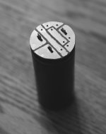
High PIV Schottky diodes made from silicon carbide (SiC) are available.
They can be quite compact too - the attached image shows a small PCB that I made which sits over the terminals of the power supply capacitor and holds 4 of the SiC rectifier diodes in a full bridge configuration.
http://www.diyaudio.com/forums/tubes-valves/280167-yukon-gold-spud-amp.html
Attachments
- Status
- Not open for further replies.
- Home
- Amplifiers
- Tubes / Valves
- 2A3 driver