Ripple current is 50mA w/ a 2.2uF cap.
4.7uF 100mA
10uF 200mA
Anything over 8uF gives a repetitive peak forward current warning for the 5AR4.
4.7uF 100mA
10uF 200mA
Anything over 8uF gives a repetitive peak forward current warning for the 5AR4.
Member
Joined 2009
Paid Member
good info !
What value does your simulations say is needed to achieve the desired B+ voltage of around 310V ?
What value does your simulations say is needed to achieve the desired B+ voltage of around 310V ?
I'm right here
The most important cap in that power supply cap is the first stage charging cap and if you are using a GZ34 you want at least 20 to 30uf..I use a 35uf in all the vintage sherwood,scott,fisher,and Eico as the first cap off the GZ34 and I have NEVER had any excessive draw or current or arcing on the rect.tube..Don't forget this tube is not a directly heated filament so it comes up slowly anyway and your not using a choke of any kind so this now becomes much more critical because you are depending on this cap for ripple reduction and storage and if you just use an 8uf cap,all you will do is reduce the ripple and almost no energy storage and the line will sag. The tube is rated for up to 60uf depending on where you run the B+ but to just put 8 or 10uf there is just going to be very anemic. I have rebuilt everything from Mc30s and to Mc60s with 100% film cap supplies and they use GZ34s in place of 5U4s a lot and then you can see some of the sherwoods with the 35uf off the GZ34 when you scroll up the page.
http://www.audioasylum.com/cgi/vt.mpl?f=tubes&m=267660
Last edited:
Here are some mc60s I rebuilt
These use a pair of 5U4s but he runs GZ34s in them and I used a 100% film cap power supply..I used the the same values Mcintosh used which was a single 80uf shared between the two 5U4s.
Mc60s New Chassis and all film cap supply - Michael Samra - Vintage Asylum
These use a pair of 5U4s but he runs GZ34s in them and I used a 100% film cap power supply..I used the the same values Mcintosh used which was a single 80uf shared between the two 5U4s.
Mc60s New Chassis and all film cap supply - Michael Samra - Vintage Asylum
Attachments

I don't subscribe to a "one size fits all" way of thinking. Honestly I don't think you looked over the proposed power supply because there are two chokes and plenty of filtering. Also comparing this class A amplifier to a bunch of vintage push pull class A/B amps with various topologies is by no means a very rational way to come up with a well designed power supply.
What value does your simulations say is needed to achieve the desired B+ voltage of around 310V ?
Between 2.2uF and 4.7uF depending on real world actual parameters. If he orders both values he should have a wide variety of options, if 2.2uF isn't enough use the 4.7uF, it should raise it about 10-12v. If that's still not enough he can parallel both and that should be plenty, simulations show 305 w/ 2.2uF and 318v w/ 4.7uF.
Member
Joined 2009
Paid Member
Single tube gain stage
Hi All,
What would that tube be to use for a single tube gain stage?
And a question here we are looking at around 4 watts per channel output , yes?
Thanks,
Ron
Hi All,
What would that tube be to use for a single tube gain stage?
And a question here we are looking at around 4 watts per channel output , yes?
Thanks,
Ron
Where is the power supply schematic and which chokes are you using?
These are my Pedersen amps that use two chokes and 4uf pio as the charging cap into an 8hy choke then a 25uf poly and then into a 30hy choke followed by a 40uf poly.These amps are dead quiet and I don't run the 6j5 because I run them with a preamp..
These are my Pedersen amps that use two chokes and 4uf pio as the charging cap into an 8hy choke then a 25uf poly and then into a 30hy choke followed by a 40uf poly.These amps are dead quiet and I don't run the 6j5 because I run them with a preamp..
Attachments

Member
Joined 2009
Paid Member
4 watts per channel output , yes?
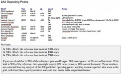
The human ear won't detect much, if any, difference between 3W and 4W because our ears operate more on a logarithmic scale - allowing us to perceive a much wider dynamic range from very soft to very loud. Pushing the 2A3 for every last drop of power won't bring that much benefit but it will stress the tube. The traditional operating point for 2A3 gives around 3.5W if I remember correctly ?
Your output transformer is designed so that when the secondary is connected to an 8 Ohm load it will reflect an impedance of 2k8 to the primary. Popular load impedance for the 2A3 varies between 2k5 and 3k so you're transformer is just right for operating the 2A3 in it's traditional range of 250V between anode and cathode with 55mA or so of idle current.
Here's some information I pulled together for my own 2A3 amplifier (attached)
Attachments
Output
Hi,
I just ask about output so I can set up my workstation where we are building this with a proper set of speakers to evaluate it's sound and performance with. The final placement of the completed amplifier will be in a different room. The intended speakers for use are floor models that really won't fit into the workstation room for proper evaluation. So I need to get something smaller for the "workstation". The listening room speakers are floor standing horns with a single [FONT=Arial,Helvetica,Geneva,Swiss,SunSans-Regular] 4.5" Fostex FE126E.
thanks!
Ron
[/FONT]
How much $ is available for the 2nd set of speakers? Getting something reasonably small and reasonably efficient is not easy, especially if the budget is severely limited.
Not low cost, but otherwise suitable is the DECWARE DM945.
Not low cost, but otherwise suitable is the DECWARE DM945.
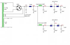
For everyone late to the party here is the power supply again. Good thing I reposted them because I noticed the last resistor wasn't correct, the 2.7k was for the 6922 pulling 8mA. The cascaded 6SN7 circuit will want a larger 6.8k resistor for the smaller 5mA draw.
There is 1.4mVrms of ripple at the 2A3 node, which should put about 15uVrms at the speaker. Basically the amp will be dead quiet. I also removed the first gain stage bypass cap to reduce gain, the ripple is so low that the decreased PSRR should not be an issue. I will repost the schematic too.
There is 1.4mVrms of ripple at the 2A3 node, which should put about 15uVrms at the speaker. Basically the amp will be dead quiet. I also removed the first gain stage bypass cap to reduce gain, the ripple is so low that the decreased PSRR should not be an issue. I will repost the schematic too.
Attachments

Last edited:
F/M/B,
The proposed PSU uses a CRC filter prior to the pseudo dual mono bifurcation via chokes. I suggest that the initial filter be CLC and that "check valve" UF4007 diodes be used at the bifurcation point. Both ripple and regulation behavior is better in CLC compared to CRC. IMO, space and performance favor a single inductor and 2X DO41 cased diodes.
The actual behavior of the PSU will be known, only after it is built and measured. PSUD2 may be a useful tool, but cut and try remains the "gold standard".
Spinning tires again here.
I don't like guessing so I calculate and simulate as much as possible. In all my builds the actual numbers in real world first edition prototypes are practically spot on from what was calculated and simulated.
If anyone else wants to draw up a schematic with actual working voltages and data feel free, but suggesting a novice to just slap together some parts and figure it out on the work bench isn't the best idea. Everything should look good on paper first so he doesn't waste his time and money is what I am trying to do here.
That would be an excellent cap Eli
I use those caps in only in the 30uf version off the 5R4 of the Heath W5ms.
That is an excellent low DCR cap and I have tested it on my LC102 for ESR and ESL and leakage is essentially nonexistent even at 65vdc over the rated voltage so that would be an excellent cap to use. Using that value will allow you to maintain a larger conduction angle as well.I understand somewhat where Mockingbird was coming from with the smaller cap if he was using a CLCL scheme but many times the spice programs don't consider dynamic conditions and I understand it's a class A circuit but you are still dealing with noise on the line today from all the digital communications and the material we listen to is much more dynamic than it was when these tubes and circuits were originally designed.. I believe your first voltage has to be as clean as it can be and supply energy to the load on demand..
If I was building this amp I would be using Schotkey diodes as they are quiet and don't sag but if I was going to use a tube rectifier,why not use 6CJ3 damper tubes. Sol MArantz did this with the model 2s and they work very well.
I agree with FMB about sparing filaments. While data sheets frequently allow +- 10%, I'm in favor of not more than 5% on the high side. 10% on the low side is (IMO) OK.
If a decision has not yet been made about the 1st filter cap. in the B+ PSU, I suggest this part. The value of that cap. is well under the limit for the 5AR4/GZ34, while its film dielectric ensures superior performance. FWIW, DC link caps. have been receiving good "press".
I use those caps in only in the 30uf version off the 5R4 of the Heath W5ms.
That is an excellent low DCR cap and I have tested it on my LC102 for ESR and ESL and leakage is essentially nonexistent even at 65vdc over the rated voltage so that would be an excellent cap to use. Using that value will allow you to maintain a larger conduction angle as well.I understand somewhat where Mockingbird was coming from with the smaller cap if he was using a CLCL scheme but many times the spice programs don't consider dynamic conditions and I understand it's a class A circuit but you are still dealing with noise on the line today from all the digital communications and the material we listen to is much more dynamic than it was when these tubes and circuits were originally designed.. I believe your first voltage has to be as clean as it can be and supply energy to the load on demand..
If I was building this amp I would be using Schotkey diodes as they are quiet and don't sag but if I was going to use a tube rectifier,why not use 6CJ3 damper tubes. Sol MArantz did this with the model 2s and they work very well.
Member
Joined 2009
Paid Member
What would that tube be to use for a single tube gain stage?
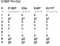
There are a few choices around and although I haven't tried them I'd be the most curious about the E180F and equivalents. There are some Russian pentodes with compatible pin-out (see table, obviously 2nd row should be 'pin 2' !) that might be fun to try in the same socket as well as the European D3a (for highest gain). If you are lazy like me you could probably run them all at similar operating points in terms of Va (anode voltage) around 150V to 170V and with similar anode load resistors such as 15k.
Attachments
^i have used the D3a, 12HL7 with very good results, they were wired as triodes...
Eli, i fully subscribe to this......simulations are fine, they will give you a fairly close idea of how a circuit will behave in real time,
simply because of the many variables involved that simulations can ever anticipate...like i used to say, having excess voltage
is better than lack of it...
otoh, fmb's psu is very good, i try to separate the left and the right B+ as much as possible,
i used 1n4007 diodes, but there are many other scheme out there like this one...
the resistors shown in the below psu might need adjustments in the actual build so get to that 2A3 sweet spot...
and if you want to use the JJ 2A3, a 350-0-350 is better if you want to run the tube at more than 15 watts plate..

The actual behavior of the PSU will be known, only after it is built and measured. PSUD2 may be a useful tool, but cut and try remains the "gold standard".
Eli, i fully subscribe to this......simulations are fine, they will give you a fairly close idea of how a circuit will behave in real time,
simply because of the many variables involved that simulations can ever anticipate...like i used to say, having excess voltage
is better than lack of it...
otoh, fmb's psu is very good, i try to separate the left and the right B+ as much as possible,
i used 1n4007 diodes, but there are many other scheme out there like this one...
the resistors shown in the below psu might need adjustments in the actual build so get to that 2A3 sweet spot...
and if you want to use the JJ 2A3, a 350-0-350 is better if you want to run the tube at more than 15 watts plate..
Member
Joined 2009
Paid Member
The D3a looks to have the best gain.
And if you want to be controversial and be derided (!) you can try using a 12AX7 - which is the tube I plan to try in my own 2a3.
And if you want to be controversial and be derided (!) you can try using a 12AX7 - which is the tube I plan to try in my own 2a3.
The D3a looks to have the best gain.
And if you want to be controversial and be derided (!) you can try using a 12AX7 - which is the tube I plan to try in my own 2a3.
just like Jadis......😀 otoh, Antiques Sounds Lab favors the 6SN7's 😉
with a triode mu of 70, much like the 12at7, but with plate resistance like that of a 6dj8, what is not to like..?
- Status
- Not open for further replies.
- Home
- Amplifiers
- Tubes / Valves
- 2A3 driver