Aluminum
Hi,
Well, aluminum it shall be. I'll draw up a layout, because I assume that placement is important. Electrical fields and such. And hopefully you all might point me in the right direction. (again)
I'm going to get the case from these guys https://www.landfallsystems.com/index.php
Anyone used them before?
Thanks!
Ron
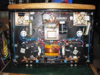
this is the underside of my 2A3 using the 12HL7 driver....
you are lucky to be living in there....great chassis...
Hi,
Well, aluminum it shall be. I'll draw up a layout, because I assume that placement is important. Electrical fields and such. And hopefully you all might point me in the right direction. (again)
I'm going to get the case from these guys https://www.landfallsystems.com/index.php
Anyone used them before?
Thanks!
Ron
you are lucky to be living in there....great chassis...
Attachments
Ron,
Get something pretty darned big, both in terms of top plate area and depth. You need room to work in. Save "shoehorn" tactics for the future, when you have experience under your belt.
The model with the front to back divider is (IMO) a good idea. Build the PSU on 1 side of the divider and the signal circuitry on the other. Aside from some shielding, the divider increases plate strength and heavy magnetics will mounted to the plate(s).
You mentioned layout. Does the term orthogonal mean anything to you? The coils of the O/P trafos can be in the same spatial plane and the coils of the power transformer should be in a different plane rotated 90o from the O/P magnetics. Ideally, a PSU filter choke will be mounted orthogonally to both the power and signal transformers. That usually works out to being on a side wall.
Ongoing
Hi,
Yes, big with things arranged as you say, orthogonal. I also like the front and back split. PS in the back as you suggest. Looking at some of the commercial products online gives a point to start. I was thinking 18 left to right by 12 front to back, at least 3 deep (inches all).
I'm going to make a cardboard and arrange the xformers, sockets, choke and things an take a snapshot. Wanting to get the spacing right for no noise and such.
I really like these things for the tubes -
More Information Page
any drawbacks? Have to see if my scope still works. Been about 8 years since it has seen any use, turned it on a numerous times just to heat it up but didn't run anything through it.
And again Eli, I really appreciate your help and input.
Ron
Chassis
Hi,
This one the Dual X. I know that I want to use good components for this, but how does one really know V-Cap, Mundorf', Jupiter, Cardas. I mean the boutique stuff - how much of it is hype? I have read on this site of persons building dead quiet Tubelab SE units and none of that is in the BOM that George suggests. But those builders really don't say if they have been using any of that stuff. My tube experiences have been with a Dared M5P ( noisey), an Antique Sound Labs 300b (slight hum - sounds 60hz, definately not 120hz ), a Cary V12 (dead quiet, very neutral with depth) and a Singlepower Extreme Platinum headphone amp (quiet, open, lots of soundstage) but that observation is sort of headphone influenced - not the quiet part. The Dared and Singlepower are PCB, the Cary and ASL are point to point, some PCB in the ASL. The only one that uses the fancy innards is the Cary and I was told the slight hum in the ASL 300b is characteristic of those tubes. So I guess I'm sort of at a lack of conclusion on the issue, which is sort of how this started for me. After trying to find the "tube sound" vs SS that is spoken about so frequently. The commercial products that I've tried have not left me with closure on the issue, so I thought if I tried myself I could get to the bottom of it. Ramble, ramble...
thanks,
Ron
Attachments
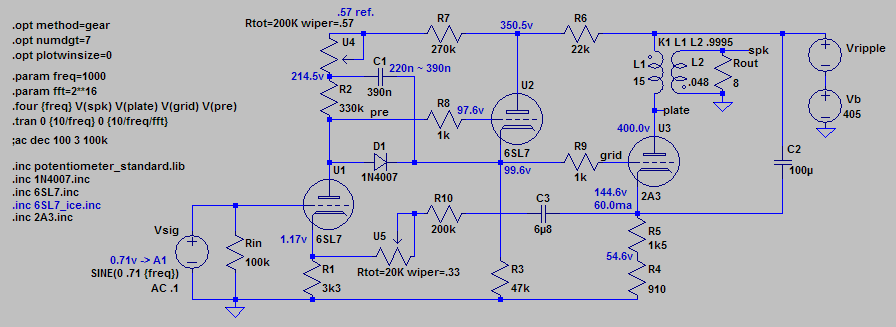
Another option just to confuse things, and as long as you don't mind burning off some energy in the output cathode resistor. It's a direct coupled amp, with very effective ps ripple cancellation. The whole amp is self regulation, once set up. Takes a while to wrap your head around the concept, but I can confirm that the design works very well. A 12AX7 can be substituted for the 6SL7 in the input position or follower position or both, with adjustments to plate and cathode resistors. Can use a pretty simple power supply and all film caps.
http://www.diyaudio.com/forums/atta...422360010-3-direct-coupled-2a3-amps-v9-lw.png
From here: http://www.diyaudio.com/forums/tubes-valves/258790-3-direct-coupled-2a3-amps-15.html#post4201171
Sheldon
http://www.diyaudio.com/forums/atta...422360010-3-direct-coupled-2a3-amps-v9-lw.png
From here: http://www.diyaudio.com/forums/tubes-valves/258790-3-direct-coupled-2a3-amps-15.html#post4201171
Sheldon
I know that I want to use good components for this, but how does one really know V-Cap, Mundorf', Jupiter, Cardas. I mean the boutique stuff - how much of it is hype?
Ron,
I completely agree with your suspicion about "hype". All 'philes, including yours truly, are vulnerable to the "Emperor's New Clothes" virus. Watch out for "Proud Papa Syndrome" too. Human beings definitely have their foibles. 🙁
As far as signal caps. go, you will do just fine with a mix of Soviet surplus K40 paper in oil (PIO) and 716P series film/foil "Orange Drops". Mixing dielectric types up allows you to hear the circuitry, not just the capacitors. A bit more costly than 716Ps, but still "reasonably" priced, are SCR (France) made tin foil/polypropylene caps. sold under the Solen and other labels. Using the SCR made film/foil stuff in combination with K40 PIOs could very well be your best bet.
Metalized polypropylene film is excellent in PSUs, but occupies huge amounts of space. Top notch, industrial grade, electrolytic caps. by Panasonic and Nichicon are very space efficient and are not particularly far behind the metalized film stuff.
The higher the filament voltage is, the more likely excessive hum will be observed, when AC is employed to energize directly heated signal tubes. As it runs on 2.5 V., the 2A3 filament on AC rarely causes hum trouble.
I like the turret board with sockets. Now if only those sockets were mica loaded phenolic, instead of ceramic. Fancy PTFE creeps and ceramic can conduct vibration, which is why I lean towards mica loaded phenolic. YMMV.
Another option just to confuse things, and as long as you don't mind burning off some energy in the output cathode resistor. It's a direct coupled amp, with very effective ps ripple cancellation. The whole amp is self regulation, once set up. Takes a while to wrap your head around the concept, but I can confirm that the design works very well. A 12AX7 can be substituted for the 6SL7 in the input position or follower position or both, with adjustments to plate and cathode resistors. Can use a pretty simple power supply and all film caps.
http://www.diyaudio.com/forums/atta...422360010-3-direct-coupled-2a3-amps-v9-lw.png
From here: http://www.diyaudio.com/forums/tubes-valves/258790-3-direct-coupled-2a3-amps-15.html#post4201171
Sheldon
Sheldon,
I don't think the 300-0-300 winding in the power trafo the OP already possesses will be good for direct coupled circuitry, as the B+ rail will be too "short".
Don't waste any money or time on boutique capacitors, in fact they probably get outperformed by normal film caps. For the power supply you want some ESR so electrolyic is a good choice, but what I have had good experience with is using inexpensive motor run caps to parallel the electrolytic at the node where the 2A3 is decoupled (where you tie the output transformer to the B+). You can see them in my amp, they are huge! I will echo Eli in that the Orange Drop 716p's are good, I also like Wima MKP a lot and used them on my last build.
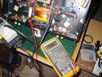
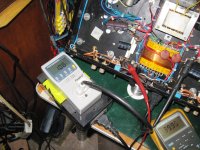
I am still drawing you up a schematic and will be done this weekend. I need some more info about the output transformers. Did they send you any specifications when you bought them? You can measure the DCR of both windings with a multimeter but I really would like to know the primary inductance. IF they didn't tell you what that is then there are ways you can measure it with a scope and a signal generator.
I am still drawing you up a schematic and will be done this weekend. I need some more info about the output transformers. Did they send you any specifications when you bought them? You can measure the DCR of both windings with a multimeter but I really would like to know the primary inductance. IF they didn't tell you what that is then there are ways you can measure it with a scope and a signal generator.
wrt to capacitors, i go by technology, anything polypropylene film is fine by me...
i also tell people not to waste their money on boutique caps, but that is only as far as i would go.....after all it is their money...
i also tell people not to waste their money on boutique caps, but that is only as far as i would go.....after all it is their money...
Sheldon,
I don't think the 300-0-300 winding in the power trafo the OP already possesses will be good for direct coupled circuitry, as the B+ rail will be too "short".
i agree...
if he can make a custom would traffo from say Edcor, that will be nice, and a hybrid graetz rectifier can be used so that the FWCT is no longer required...
grid bias for the 2A3 is in the -45 volt range, so for me any driver than can run plate voltages of around 250 volts is quite enough....
the 2 main issues for input tube options are gain neded with resprct to the input,
and dynamic capacirance load at the input of the 2a3, that loading input-driver tube.
...
Cdyn is for determining minimum output resistance of input-driver tube as generator,
for high Fo limit.
Good choice of mu of the tube is to match with input signal max value p-p. That is because too much gain leeds to input stage for overaplifing, giving the pot slider always in very low position...
...
these designs with high mu tubes are wrong. the amplification is huge, internal resisrance of the tubes are high, making them high impedance generators, causing the possibile loss in the highs, before output transformer did the same thing, resulting in phase degrading... 🙂
...
If You go for -45V negative grid bias. And some contemporary sources outputs up to 3V p-p signal. Then You will have roughly, (2 x 45V p-p) / 3V=30.
in that case 30 X is more than enough for amplification of the stage before 2A3.
And You can use this amp without preamp with CD player or DACs...
...
With preamp in chain, that additionally amplifying the signal -A, (Gain) of the first stage could be even less than 30 times.
...
Cgp (grid to plate) = 16.5 pF
Cgc (grid to cathode) = 7.5 pF
Mu = 4.2 (in the circuit Gain -A, will be less than mu
Cdyn = (abs(-A) +1) x Cgp) + Cgc
That is about MAX
Cdyn = 5.2 x 17.5pF + 8.5pF = 82pF cca.
(with 1pF added as socket capacitances, and max mu...)
so You will need less than 14.825 ohm, roughly less than 15Kohm Rgenerator for Fo=131KHz -3db
Rgen=1 / (2 x PI x Fo x Cdyn)
(Input R of the 2A3 is high value so it is not changing significantly the picture...)
...
R of the generator will be always the smaller than internal resistance of the tube. Ri.
Because we have Rload in lets say parallel with Ri like some close value for Rgen.
...
Now You need tube with 30 x of mu, Ri <= 15K
for good input/driver tube for 2A3.
...
If You go for preamplifier before 2A3 amp then You will need less amplification of the first stage for 2A3 tube. 6J5 with much less Ri than needed, will be the just fine like more tubes choices you have. one section of 6SN7 🙂
...
Biasing of the input tube shoul be in respect to the signal value coming to the grid.
So if You are using input without preamp biasing should be more than say -3V. With preamp that is larger in abs value say -6V to -10V. Not to overload input tube with the larg signal.
.
cheers 🙂
Last edited:
allenrssob (Ron)
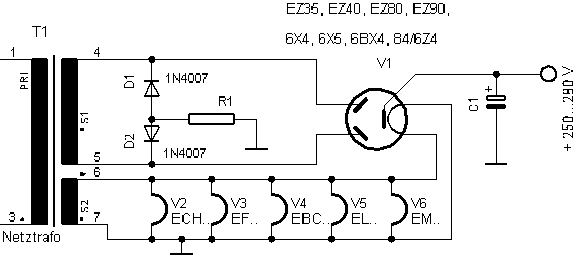
I think that this circuit (image below) might be a better choice for a first project. The tubes are easier to get hold of and are cheaper. Also battery bias is a bit awkward. This is actually a very generic circuit (its sold by Sun audio for about $3000 !) but it has a wonderfully full sound.

I think that this circuit (image below) might be a better choice for a first project. The tubes are easier to get hold of and are cheaper. Also battery bias is a bit awkward. This is actually a very generic circuit (its sold by Sun audio for about $3000 !) but it has a wonderfully full sound.
You can, more or less, retain the topology by using a 6SN7 twin triode for voltage amplification. The circuit shows truly fixed, battery, bias on the 2A3's grid. As DHTs, like the 2A3, are particularly vulnerable to runaway, when fixed bias is employed, I'd like to see the value of the 2A3's grid resistor reduced. To prevent voltage amplifier gain loss, insert a DC coupled IRFBC20 source follower between the voltage gain circuitry and the 2A3. Think of the FET as a heaterless pentode. For several reasons, including great ease of use, a well selected FET makes a superior voltage follower. Read MOSFET Follies. Experience has shown that protective 15 V. Zener diode between the gate and source electrodes of the IRFBC20 is important protection against start up transients.
Build a SS rectified negative supply for 2A3 bias and use trim pots., to exactly control O/P tube "idle" current.
Eli - I think Ron is saying that he's a novice with limited experience in tube circuits. When I was a novice some years back I would have understood 10% of what you advise in your response (its all good stuff but probably un-intelligible to a novice).
Sean
the 2 main issues for input tube options are gain neded with resprct to the input,
and dynamic capacirance load at the input of the 2a3, that loading input-driver tube.
...
Cdyn is for determining minimum output resistance of input-driver tube as generator,
for high Fo limit.
Good choice of mu of the tube is to match with input signal max value p-p. That is because too much gain leeds to input stage for overaplifing, giving the pot slider always in very low position...
...
these designs with high mu tubes are wrong. the amplification is huge, internal resisrance of the tubes are high, making them high impedance generators, causing the possibile loss in the highs, before output transformer did the same thing, resulting in phase degrading... 🙂
...
If You go for -45V negative grid bias. And some contemporary sources outputs up to 3V p-p signal. Then You will have roughly, (2 x 45V p-p) / 3V=30.
in that case 30 X is more than enough for amplification of the stage before 2A3.
And You can use this amp without preamp with CD player or DACs...
...
With preamp in chain, that additionally amplifying the signal -A, (Gain) of the first stage could be even less than 30 times.
...
Cgp (grid to plate) = 16.5 pF
Cgc (grid to cathode) = 7.5 pF
Mu = 4.2 (in the circuit Gain -A, will be less than mu
Cdyn = (abs(-A) +1) x Cgp) + Cgc
That is about MAX
Cdyn = 5.2 x 17.5pF + 8.5pF = 82pF cca.
(with 1pF added as socket capacitances, and max mu...)
so You will need less than 14.825 ohm, roughly less than 15Kohm Rgenerator for Fo=131KHz -3db
Rgen=1 / (2 x PI x Fo x Cdyn)
(Input R of the 2A3 is high value so it is not changing significantly the picture...)
...
R of the generator will be always the smaller than internal resistance of the tube. Ri.
Because we have Rload in lets say parallel with Ri like some close value for Rgen.
...
Now You need tube with 30 x of mu, Ri <= 15K
for good input/driver tube for 2A3.
...
If You go for preamplifier before 2A3 amp then You will need less amplification of the first stage for 2A3 tube. 6J5 with much less Ri than needed, will be the just fine like more tubes choices you have. one section of 6SN7 🙂
...
Biasing of the input tube shoul be in respect to the signal value coming to the grid.
So if You are using input without preamp biasing should be more than say -3V. With preamp that is larger in abs value say -6V to -10V. Not to overload input tube with the larg signal.
.
cheers 🙂
6N7 w/ triodes in parallel

OPT info
Hi,
There is no paper diagram in with the OPTs.
The only info I have is 2.8k secondary 8 ohms.
I can call Sophia what information would I ask them for?
Or maybe just better to check them anyway.
I have a signal gen and scope.
I was looking at this link
https://video.search.yahoo.com/vide...=1457209293&fr2=p:s,v:v&fr=yfp-hrtab-901&tt=b
Is this the correct way for me to do the bias calculations?
Another question I have is about the dual triode. Obviously they work, but when electrons flow from the cathode(s). how do they "go" to the correct plate?
If you have lets say side A cathode releasing, and side B releasing how do they arrive to the plates for side A and side B respectively in the correct proportion as to how they are being emitted. What keeps some side A electrons straying to the side B plate? Maybe a stupid question, but I have to ask. And the same with the grids, what keeps the grid bias on each side of the tube from influencing the electron cloud(s) of the respective cathodes?
Please be patient and don't broil me to much.
We all start in this somewhere.
Thank you all for your help!
Ron
- Status
- Not open for further replies.
- Home
- Amplifiers
- Tubes / Valves
- 2A3 driver