Thx - the fun never should stop! 😉I wish you another successful build!🙂
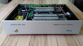
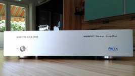
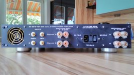
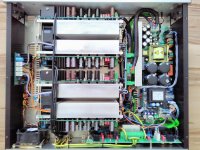
SA2015 - 4 channel - active cooling - finished and running
SA2015 V-MOSFET up and running all 4 channels! 🙂
Absolutely clear and perfect sound as expected! 🙂
Cooling doesn't need any extra fans, extra plastic helpers. It just works perfectly and there are no temperature hotspots detectable using my IR difference thermometer and for deeper inspection using the bimetal probe.
BR, Toni
P.S.: some cables are without extra isolation - this will be changed the next days of course! 🙂
Attachments


You must be preparing for Atmos 12-16 channels with all these builds! Well done. Now if only Modu would get a move on with my enclosure....
You must be preparing for Atmos 12-16 channels with all these builds! Well done. Now if only Modu would get a move on with my enclosure....
Thx! Since 2011 I have successfully built:
- SA2011-AB2: 2 channel LME49830, 2 pairs V-MOSFET, 2 x 120W@8R
- SA2012-AB4-GC800: 4 channel bridged LM3886, 4 x 100W@8R
- SA2012-AB4-1000: 4 channel LME49830, 3 pairs V-MOSFET, 4 x 180W@8R
- SA2013-AB2-800: 2 channel 8 pairs BJT, 2 x 220W@8R, 2 x 440W@4R
- SA2014-AB4-1200: 4 channel 8 pairs BJT, 4 x 220W@8R, 2 x 440W@4R (cont. 4R only 2 channels)
- SA2015-D4-800: 4 channel bridged Class-D LiteAmp, 4 x 180W@8R
- SA2015-AB4-300: 4 channel 3 pairs V-MOSFET, 4x 70W@8R, 4 x 140W@4R
A total of 24 channels ... 😉 ... built just 4 fun ...
In between my Class AB and Class-D builds I have made the electronics for a friend of mine for his 2 channel class A 50W@8R and 2 monoblock Class A 100W@8R amps...
BR, Toni
P.S.: As you can see, I'm no a fan of Class A amplifiers... 😉.
Last edited:
Great!!!SA2015 V-MOSFET up and running all 4 channels! 🙂
Absolutely clear and perfect sound as expected! 🙂
Cooling doesn't need any extra fans, extra plastic helpers. It just works perfectly and there are no temperature hotspots detectable using my IR difference thermometer and for deeper inspection using the bimetal probe.
BR, Toni
P.S.: some cables are without extra isolation - this will be changed the next days of course! 🙂
A piece of art!
Attachments
Hi,
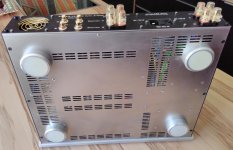
just one question: Why did You mount the rear fan as it is?
Sajti
What exactly do you want to know?
What exactly do you want to know?
The usual way is that the finger guard is outside of the box, and the fan is mounted on the back panel of the box. Your way is more complicated.
Sajti
The usual way is that the finger guard is outside of the box, and the fan is mounted on the back panel of the box. Your way is more complicated.
Sajti
For PC style optic this may be OK and if you own a finger guard which fits perfectly. This recycled finger guard was for 70mm fan and I need to bend the mounting wires. Hence the mounting inside.
BR, Toni
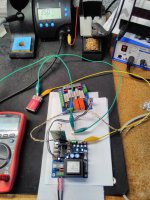
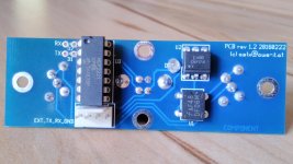
housekeeping circuits - final hardware version 4.3
... my new programmer arrived. Now there is no more need for a parallel port. I'm glad that It works native under Linux using the MPLAP IPE tool ... 🙂
Software for housekeeping hardware version v4.3 is finished - only need some more days to be tested... 😉
BR, Toni
... my new programmer arrived. Now there is no more need for a parallel port. I'm glad that It works native under Linux using the MPLAP IPE tool ... 🙂
Software for housekeeping hardware version v4.3 is finished - only need some more days to be tested... 😉
BR, Toni
Attachments

housekeeping circuits - final hardware version 4.3
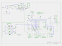
Updated schematics and BOM for the 115VAC / 230VAC version controller board. Mains inrush control board will follow ...
NOTE: Schematics and/or pcb gerber files are free to use only for non commercial DIY projects.
WARNING: this circuit provides very high AC voltages and is therefore very dangerous and can be lethal. I am not responsible for any costs, damage and/or injury using these schematics. Do not use this schematics if you do not have the necessary experience and knowledge.
Attachments

Last edited:
housekeeping circuits - final hardware version 4.3
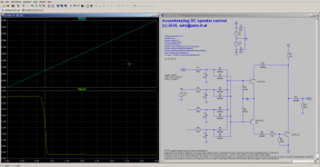
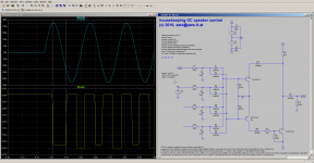
Speaker DC simulation. Note: housekeeping controller can be very fine adjusted in software how long a DC event must be viewable to be recognized as DC on output. In the example you can see a higher power 4Hz output generates a worst case 100ms DC event.
Speaker DC simulation. Note: housekeeping controller can be very fine adjusted in software how long a DC event must be viewable to be recognized as DC on output. In the example you can see a higher power 4Hz output generates a worst case 100ms DC event.
Attachments
housekeeping circuits - final hardware version 4.3
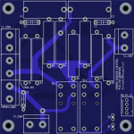
... attached the relay board.
It is possible to use the PCB also for 115V AC mains:
NOTE: Schematics and/or pcb gerber files are free to use only for non commercial DIY projects.
WARNING: this circuit provides very high AC voltages and is therefore very dangerous and can be lethal. I am not responsible for any costs, damage and/or injury using these schematics. Do not use this schematics if you do not have the necessary experience and knowledge.
... attached the relay board.
It is possible to use the PCB also for 115V AC mains:
- resistor R1 - R8 values have to be reduced to 47R - 68R
- max. 600VA toroids if copper thickness of pcb is 70µ.
- other relay types are needed with higher current at 115V AC
NOTE: Schematics and/or pcb gerber files are free to use only for non commercial DIY projects.
WARNING: this circuit provides very high AC voltages and is therefore very dangerous and can be lethal. I am not responsible for any costs, damage and/or injury using these schematics. Do not use this schematics if you do not have the necessary experience and knowledge.
Attachments
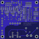
housekeeping circuits - final hardware version 4.3
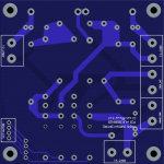
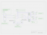
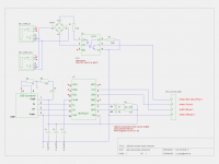
USB control and remote power on module:
NOTE: Schematics and/or pcb gerber files are free to use only for non commercial DIY projects.
USB control and remote power on module:
NOTE: Schematics and/or pcb gerber files are free to use only for non commercial DIY projects.
Attachments
-
usb_and_remote_control_schematic.pdf37.9 KB · Views: 336
-
 usb_and_remote_control_schematic.png131.8 KB · Views: 591
 -
 usb_and_remote_control_bottom.png40.1 KB · Views: 369
 -
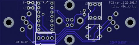 usb_and_remote_control_top.png36 KB · Views: 435
 -
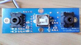 usb_and_remote_control_2.jpg221.3 KB · Views: 466
 -
 usb_and_remote_control_1.jpg197.8 KB · Views: 745
Astx,
I prefer to use a series set of limiting resistor. eg. 4 off 10r 5W gives an equivalent 40r 20W that uses very thick wire in the wire wound resistor elements.
Using a paralleled arrangement of 4off 160r 5W for the same 40r 20W uses lots of very thin wire for the elements.
I believe that the thick wire is more tolerant of current transients even though it is being asked to pass all the current compared to the paralleled arrangement where each resistor passes only 25% of the current.
The series arrangement also allows Builders to substitute Power Thermistors for the resistors if they prefer.
Astx,
I prefer to use a series set of limiting resistor. eg. 4 off 10r 5W gives an equivalent 40r 20W that uses very thick wire in the wire wound resistor elements.
Using a paralleled arrangement of 4off 160r 5W for the same 40r 20W uses lots of very thin wire for the elements.
I believe that the thick wire is more tolerant of current transients even though it is being asked to pass all the current compared to the paralleled arrangement where each resistor passes only 25% of the current.
The series arrangement also allows Builders to substitute Power Thermistors for the resistors if they prefer.
Maybe you are right. I have taken the decision to go for parallel VITROHM a long time ago due to the high peak power feature. The peak power is very high using VITROHM KH208-8 series mostly not dependent on their wire thickness (datasheet). Up to 500W peak for a short time period for e.g. 200ms. If you allow cooling down (which is controlled in software - cooling time for repowering can be configured in sec steps) you can do this on a regularly basis. One failed resistor in a series arrangement and you need maintenance. Using 4 smaller resistors paralleled is tolerant for up to 2 defective resistors.
The circuit is tolerant for using NTCs instead too. The software controlled delay can help to avoid too early repowering and keep the NTC cool enough to do its work.
BR, Toni
Last edited:
- Home
- Amplifiers
- Solid State
- 2stageEF high performance class AB power amp / 200W8R / 400W4R