That's great. Put it into XSim and re-examine the crossover. Did you get impedance for both drivers? You should, then just add them to the individual drivers in XSim.
All that's missing then is the FR of the woofer against the wall. Measure at the same relative voltage as before, at the same distance, on tweeter axis.
If you do that then your XSim will be entirely accurate. 🙂
Best,
Erik
All that's missing then is the FR of the woofer against the wall. Measure at the same relative voltage as before, at the same distance, on tweeter axis.
If you do that then your XSim will be entirely accurate. 🙂
Best,
Erik
Thanks for this guide!Here is a measurement guide I made a while ago for ARTA that is fairly easy to follow. Just dropping this in case a different perspective from a different program would be useful. From the quick peruse of this thread it seems like Sultanen is being guided in the correct way but the measurements seem a little lacking.
measurement guide
This may help! So good luck 🙂
I have been playing with ARTA quite a few hours today, i moved the speaker to the garage and used a car amp to power it at 1,837V. The speaker was positioned in a corner with about 1,1m to both walls. I used the laptops soundcard for input and output instead of USB soundcard becous i had some issues there.
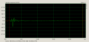
I kept the starttime on the impulse the same for all far field measurements.
I hope i did some of this the right way, otherwise please tell me 🙂
I did the following measurments with hopefully decent impulse "intervals"
Far field 1m from speaker, never moved mic or speaker:
-Tweeter
-Woofer
-Tweeter+woofer
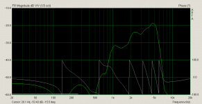
-Woofer wall - listening position
Near field 10cm from cone:
-Tweeter
-Woofer
-Woofer wall - listening position

Attachments
-
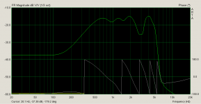 2016-02-07 20_30_48-woofer-far-field-FR-ph-wall.png33.1 KB · Views: 226
 -
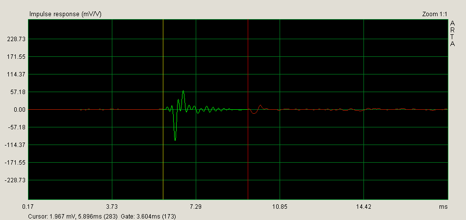
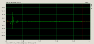
 2016-02-07 18_55_12-tweeter-far-field-impulse.png17.5 KB · Views: 215
 -
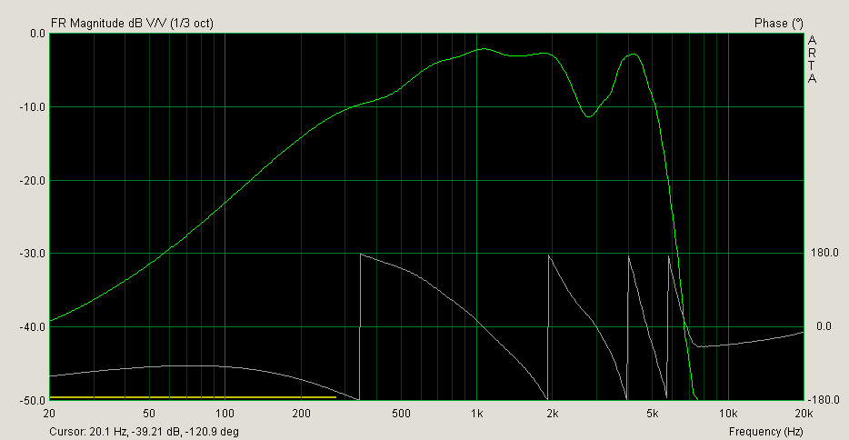
 2016-02-07 18_55_27-tweeter-far-field-FR-ph.png32.5 KB · Views: 204
 -
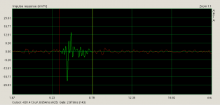
 2016-02-07 18_58_09-woofer+tweeter-far-field-impulse.png17.4 KB · Views: 214
 -
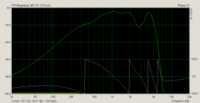
 2016-02-07 18_58_20-woofer+tweeter-far-field-FR+ph.png33.9 KB · Views: 212
 -
 2016-02-07 19_16_37-tweeter-near-field-impulse.png16.5 KB · Views: 217
 -
 2016-02-07 18_58_20-tweeter-near-field-FR+ph.png30.8 KB · Views: 218
 -
 2016-02-07 19_22_20-woofer-near-field-impulse.png17.5 KB · Views: 214
 -
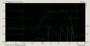
 2016-02-07 19_22_31-woofer-near-field-FR+ph.png34.2 KB · Views: 227
 -
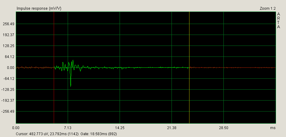
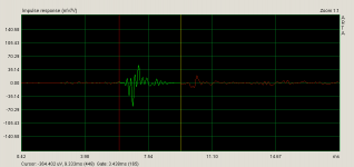
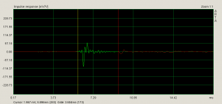
 2016-02-07 20_30_30-woofer-far-field-impulse-wall.png19.4 KB · Views: 212
Last edited:
The last uploads, was limited to 10 in last post.
Attachments
-
 2016-02-07 18_53_05-woofer-far-field-FR-ph.png32.1 KB · Views: 216
 -
 2016-02-07 18_52_50-woofer-far-field-impulse.png16.4 KB · Views: 220
 -
 2016-02-07 20_36_27-woofer-near-field-impulse-wall.png16.5 KB · Views: 217
 -
 2016-02-07 20_36_37-woofer-near-field-FR-ph-wall.png35.3 KB · Views: 216
 -
frd.zip65.7 KB · Views: 40
Last edited:
Hi
You have been busy!
I have had a look at your measurements and I have a few comments.
The zma files show an Rdc around 110R for both woofer and tweeter. This can't be correct.
You measured the nearfield response at 10cm. It is best to get as close to the dust cap of the woofer as you can without the mic touching the speaker - say 4mm.
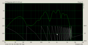
The nearfield FR of the woofer has a 17dB dip between 70Hz and 700Hz. Someone else might be able to explain what is happening here.
I can't find any mention of which microphone you are using for your measurements. Is it calibrated?
Regards
Robert
You have been busy!
I have had a look at your measurements and I have a few comments.
The zma files show an Rdc around 110R for both woofer and tweeter. This can't be correct.
You measured the nearfield response at 10cm. It is best to get as close to the dust cap of the woofer as you can without the mic touching the speaker - say 4mm.
The nearfield FR of the woofer has a 17dB dip between 70Hz and 700Hz. Someone else might be able to explain what is happening here.
I can't find any mention of which microphone you are using for your measurements. Is it calibrated?
Regards
Robert
Yea, i try to get something done at least =) Even if i have to go back and redo whatever i misunderstood.Hi
You have been busy!
I have had a look at your measurements and I have a few comments.
The zma files show an Rdc around 110R for both woofer and tweeter. This can't be correct.
You measured the nearfield response at 10cm. It is best to get as close to the dust cap of the woofer as you can without the mic touching the speaker - say 4mm.
The nearfield FR of the woofer has a 17dB dip between 70Hz and 700Hz. Someone else might be able to explain what is happening here.
I can't find any mention of which microphone you are using for your measurements. Is it calibrated?
Regards
Robert
Ah, i figure that i get those values because using a 99ohm resistor in the measurement?
Okey, so i should redo near field measurements then 😛
The microphone im using is a Harman Kardon microphone like this one: New Harman Kardon EZ Set EQ Calibration Microphone | eBay
I actually have no clue of the performance of that thing but it was the best thing i could find laying around.
Ah, i figure that i get those values because using a 99ohm resistor in the measurement?
Are you using REW to measure impedance? Using a 99R sense resistor shouldn't give you a 110R Rdc for the speaker if you follow the method in the help file.
I think you need to sort out the microphone before making any more measurements.
It looks like the mic you are using is designed to connect to a HK AVR to calibrate the room response. I am not sure that this is a calibrated mic. There may be a calibration file pre-installed in the AVR to allow for variations in frequency response. I am not sure how linear the response will be for your use
Robert
I will take another look at the impedance measurements then.Are you using REW to measure impedance? Using a 99R sense resistor shouldn't give you a 110R Rdc for the speaker if you follow the method in the help file.
I figured that it was decent at least but its probably not calibrated.I think you need to sort out the microphone before making any more measurements.
It looks like the mic you are using is designed to connect to a HK AVR to calibrate the room response. I am not sure that this is a calibrated mic. There may be a calibration file pre-installed in the AVR to allow for variations in frequency response. I am not sure how linear the response will be for your use
Robert
Would it be good enought for me if i bought a Panasonic Electret Capsule WM-61A and did a DIY mic? I figure its cheap and from what i have read its quite well behaved even if its not calibrated?
Would it be good enought for me if i bought a Panasonic Electret Capsule WM-61A and did a DIY mic?
That's what I use
Robert
Would it be good enought for me if i bought a Panasonic Electret Capsule WM-61A and did a DIY mic? I figure its cheap and from what i have read its quite well behaved even if its not calibrated?
WM61A capsules are typically fairly peaky (but well-behaved) in the treble.
Look here if you go that route
John Conover: Using the Panasonic WM61A as a Measurement Microphone
I will try to do this as an exercise until i get a new microphone. Lets do this all the way now and the mic is probably the thing i have the least control of atm? =)That's great. Put it into XSim and re-examine the crossover. Did you get impedance for both drivers? You should, then just add them to the individual drivers in XSim.
All that's missing then is the FR of the woofer against the wall. Measure at the same relative voltage as before, at the same distance, on tweeter axis.
If you do that then your XSim will be entirely accurate. 🙂
Best,
Erik
That's what I use
Robert
WM61A capsules are typically fairly peaky (but well-behaved) in the treble.
Look here if you go that route
John Conover: Using the Panasonic WM61A as a Measurement Microphone
Great! I will order this from a shop here in Sweden that had them in stock 🙂 I have seen soo many different circuits of the amplifier to this mic and modifications like System Test
Have any suggestions of what to go for? I will probably use it together with my UCA202.
I used this design published on the Gainphile Blog but I think I will build the amplifier shown in fig IV of the article Ron E posted.
Have you sorted out your impedance measurements yet?
Robert
Have you sorted out your impedance measurements yet?
Robert
I saw that one and really liked the simplicity of it! So you would argue that its not worth doing the Linkwitz mod to remove the internal amplifier of the mic?I used this design published on the Gainphile Blog but I think I will build the amplifier shown in fig IV of the article Ron E posted.
Have you sorted out your impedance measurements yet?
Robert
Are you using only the design from Gainphile Blog at the moment? I figure that i might let it be good enought to do that and then connect it to my UCA202 and take my measurements? Im not affraid of making something more elaborate but it would be good to know that spending all that time on the mic will actually give me something in return =)
About the impedance measurements, i will try to get them sorted tonight. Hopefully i can find the reason for the high values. I should get something like 8ohm rather than 107 right?
Yes. I constructed the mic the same way using a chopstock. I attached it to a small enclosure containing the components and battery with a switch so I can disconnect the battery when I am not taking measurements.Are you using only the design from Gainphile Blog at the moment?
By the way, what 10uF bipolar cap did you use?
I am away from home at the moment so I can't check the capacitor but looking at the circuit again one end of the capacitor is connected to +ve of battery through 2.2 K resistor so is a bipolar needed?
The main problem I encountered was the lack of sensitivity of the mic. I ended up using the aux input on a preamp to boost the signal before the sound card. That's why I think I will construct the amp from the John Conover reference.
Robert
Okey, that sounds convenient =)Yes. I constructed the mic the same way using a chopstock. I attached it to a small enclosure containing the components and battery with a switch so I can disconnect the battery when I am not taking measurements.
The lack of sensitivity really sounds like an issue. I think i will look into what options there is on this mic, compared to finding information about the woofer in my speakers there is a huge amount of info and DIYing around this mic 🙂I am away from home at the moment so I can't check the capacitor but looking at the circuit again one end of the capacitor is connected to +ve of battery through 2.2 K resistor so is a bipolar needed?
The main problem I encountered was the lack of sensitivity of the mic. I ended up using the aux input on a preamp to boost the signal before the sound card. That's why I think I will construct the amp from the John Conover reference.
Robert
Im not sure about the bipolar cap. I don't know if its important for the measurements to keep it as a specific type, its easy to make a bipolar cap from 2xpolar electrolytic caps but that might be entirely wrong for the application..
Im not sure about the bipolar cap. I don't know if its important for the measurements to keep it as a specific type, its easy to make a bipolar cap from 2xpolar electrolytic caps but that might be entirely wrong for the application..
The capacitor is there pass the ac sound signal but block the battery dc from the input of the sound card. You don't need any special type.
Robert
The capacitor is there pass the ac sound signal but block the battery dc from the input of the sound card. You don't need any special type.
Robert
Okey, thanks =)
I have ordered 2 mics now btw, will be fun to start playing with them, i just need to sort out the order for amp as well
Last edited:
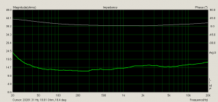
So, now i finally have some impedance data thats closer to the values we want. Does this look okey now? =)
Woofer in box

Tweeter in box

Woofer in box
Tweeter in box
Attachments
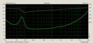
Haha, no way. 🙂
Driver should be around 3-8 Ohms at the bottom. 🙂
Manufacturers usually get the impedance charts right, but little else is trustworthy. 🙂 Compare your tweeter with the spec sheet.
Best,
Erik
Driver should be around 3-8 Ohms at the bottom. 🙂
Manufacturers usually get the impedance charts right, but little else is trustworthy. 🙂 Compare your tweeter with the spec sheet.
Best,
Erik
- Status
- Not open for further replies.
- Home
- Loudspeakers
- Multi-Way
- 2 Way speakers - Suggestions on improvements?