Im using Tombstone but i have Room EQ Wizard installed on the computer aswell so ill use that since it had a nice guide for impedance measurments 🙂What program are you using to measure your frequency plots? Maybe it will measure impedance too.
Robert
Sultanen, I appreciate you are just finding your way around the software at the moment, but anything above 2.7mH bass coil, and 0.68mH shunt coil on the tweeter is just outside the ballpark! 😀
Haha, i have literally no idea of whats resonable values here, im just playing around with the software trying to get a flat curve, thats why i need your help 😀Sultanen, I appreciate you are just finding your way around the software at the moment, but anything above 2.7mH bass coil, and 0.68mH shunt coil on the tweeter is just outside the ballpark! 😀
Your the master, im the slave, so to speak ^^
Sultanen, I'd read up on baffle step compensation. 🙂
To put it simply, put a coil in series with the woofer. Increase until it flattens out. Pad tweeter down to match level. 🙂
There's a couple of ways of doing a BSC circuit. One involves parallel a big coil with a resistor. I don't like it because of so much heat in the resistor. Another way is to use a big coil, and parallel that with a cap if the high frequency of the driver falls off too soon.
I'm not an expert in that, but I think you could try either method. Try this calculator.
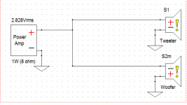
Free air frequency: 51HzTo see what is happening with the bass start by measuring the impedance of the bass driver out of the enclosure and then in the enclosure without any crossover attached. This will tell you the Fr of the speaker in free air and also in the box.
Robert
Will do in box tomorrow =)
I will read and play around with it.Sultanen, I'd read up on baffle step compensation. 🙂
To put it simply, put a coil in series with the woofer. Increase until it flattens out. Pad tweeter down to match level. 🙂
There's a couple of ways of doing a BSC circuit. One involves parallel a big coil with a resistor. I don't like it because of so much heat in the resistor. Another way is to use a big coil, and parallel that with a cap if the high frequency of the driver falls off too soon.
I'm not an expert in that, but I think you could try either method. Try this calculator.
As you may have seen i tried this in some simulations but im not getting it as flat as i would like it to be.
If you could find time to add the woofer into Xsim and get something in the ballpark of what we want i would be really happy! 😀 But i will read on and try to grasp the concept and execution of it =)
Last edited:
I will read and play around with it.
As you may have seen i tried this in some simulations but im not getting it as flat as i would like it to be.
If you could find time to add the woofer into Xsim and get something in the ballpark of what we want i would be really happy! 😀 But i will read on and try to grasp the concept and execution of it =)
Zip up your XSim project file and let me look at it. Attach it to the thread.
Best,
Erik
Yeya 😀Zip up your XSim project file and let me look at it. Attach it to the thread.
Best,
Erik
Here is a zip of the base design, Tweeter+Woofer. Woofer has inverted polarity and a delay of 0.77in.
Attachments
Got it. When you measured the woofer for XSim, where was the speaker? Against the wall or middle of the room?
Best,
Erik
Best,
Erik
Also, I think we're missing the phase data for the FRD files. 🙂 I don't buy the phase plots I'm seeing.
Here's what I came up with. There are 3 cheats.
1. The 0.1mH Inductor is phony, but meant to represent the L of the voice coil.
2. The 56 Ohm resistor is phony, just there to make XSim see the tweeter as a 7 Ohm.
3. I've added an impedance curve from the Woofer from a Focal I have that has similar specs. Or might be. Who knows. 🙂 IT's a total "Hail Mary" like they say in US football when you have nothing to loose and you throw a 50 yard pass in the hopes you could win the game.
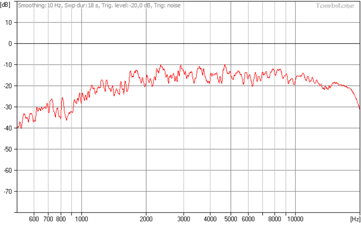
Last question, are you sure you measured the tweeter with the microphone pointing straight at it? I'm a little worried the top of the FR is a little too steep.
Here are the pics. You won't get agreement with the FR because you don't have my impedance file. I'll send it all to you when I figure out how to upload.


This would be much more accurate if we had real impedance curves instead of the one I borrowed from a Focal driver. It matters most for the woofer, but the tweeter as well.
Let's go over the schematic.
Tweeter
I used two "CircuitBlocks", a High Pass 2nd Order and an L-Pad. R2 and L3 are just there to make XSim pretend the tweeter is closer to the real one. R2 makes the effective 8 Ohms 7. The 0.1mH inductor is straight from the spec sheet. In real life, you would not buy these, they are part of your tweeter already.
C4 is an equalizer that's helping to boost the top end of the tweeter. It's essentially a high-pass filter around that resistor. We're cheating because that resistor is both part of the L Pad and part of the EQ circuit. It happened to work, but in some cases you'll need to break that resistor down into 2 and bypass only one of them. Examine the FR as you remove it and add it back in. Also examine the Component Voltage graph for S1. You will see the voltage at the tweeter change as this value changes.
Woofer
This one is not going to match real life very well for two reasons. One, we are using phony impedance curves, and two, I suspect the FR was from free-space. We need the FR from the speaker against the wall for the woofer to be accurate. Still it's a good example.
L1/R1 are the Baffle Step Compensation, but also part of the low pass network. C1 is the second pole. C3/R6 are a Zobel network I threw in. It keeps the impedance of the woofer low despite the inductance. To see the effect, pull out the tweeter high pass block, and add and remove the ground at R6. Look especially at the impedance curve. It has the end result of helping to keep the downward woofer slope stay consistent, but also changes the overall phase of the woofer, so sometimes this circuit can be played with to get better phase matching.
R5 is an impedance compensating circuit. When I looked at the impedance plot there were some very high numbers. If you were using tubes it would be mandatory. With solid state it's optional, but it can prevent ultrasonic ringing, keeping your amp from working extra and some say makes it sound better. Again, try adding and removing it while looking at the impedance plot.
Best,
Erik
Last edited:
Okey, now i've done in box measurements as well and i got 80HzFree air frequency: 51Hz
Will do in box tomorrow =)
Good afternoon and thanks for all the posts! Sorry that i did not answer earlier, i did in box frequency measurement and also another tweeter response curve to answer this question 🙂Last question, are you sure you measured the tweeter with the microphone pointing straight at it? I'm a little worried the top of the FR is a little too steep.
I actually noticed that the microphone was not really aligned with the casing so i tried to correct that.
I set a frequency of 1000Hz and measured the dB of the mic with the old placement and got 62,9dB, when i got the microphone into the most optimal angle i could find i got 64,8dB so its a bit of a difference.
I will also get the FRD file in a few minutes =) Will answer all of the other posts after that.
EDIT - FRD file attached. Its only 500Hz-20kHz, hope that will work okey =)
Attachments

Last edited:
It was in the middle of the free space in between tv and the sofa, 1.2m to the wall from the back and 1.1m to the wall on one side, about the same to the sofa on the other side.Got it. When you measured the woofer for XSim, where was the speaker? Against the wall or middle of the room?
Best,
Erik
Yea, there is not phase data there, becous i had no idea that it i should have put it there or how to do it 😛Also, I think we're missing the phase data for the FRD files. 🙂 I don't buy the phase plots I'm seeing.
By phony, you mean that they should not be there in the final design?Here's what I came up with. There are 3 cheats.
1. The 0.1mH Inductor is phony, but meant to represent the L of the voice coil.
2. The 56 Ohm resistor is phony, just there to make XSim see the tweeter as a 7 Ohm.
3. I've added an impedance curve from the Woofer from a Focal I have that has similar specs. Or might be. Who knows. 🙂 IT's a total "Hail Mary" like they say in US football when you have nothing to loose and you throw a 50 yard pass in the hopes you could win the game.
I could try to get an impedance curve if its important, i have made so many measurements on these drivers now, a few more cant be to bad 😛 But i love your comparison 😀
You need to re-take the FRD for the woofer alone, and it needs to be at least from 40 Hz.
Your measurement tool should allow you to export it. If not, oh well. 🙂
The crossover design I came up with was for the FR you had, which is in the middle of the room. And if you will listen with the speaker there it will be fine. 🙂 But the problem is you are listening with the speaker against the wall.
The wall will re-inforce the bass and there will be less to compensate for. That will have a cascading effect on the Baffle step, the second pole, and the tweeter level.
I mentioned this many pages ago, that to actually design the crossover you'd want to get the FR for the woofer in it's normal place. When you re-measure you'll see how big a difference this is.
Best,
Erik
- Status
- Not open for further replies.
- Home
- Loudspeakers
- Multi-Way
- 2 Way speakers - Suggestions on improvements?