Import the graphs into XSim. Xsim uses an FRD format. IT's extremely simple.
Hz,level
HOwever, level needs to be a positive value. You may need to add some bogus number to each of the results. Like, add 90 or something to get there.
This may be very easy to do using an online spreadsheet like Google sheets, or any other spreadsheet. It's essentially a CSV file (Comma Separated Values) with a different extension.
Erik
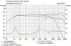
I got the last set of curves into Xsim with SPL Copy =)
Added 90dB so the range i used was -60dB->30dB, 0dB -> 90dB


Also:
Inceased the amp to 100W to see more of the curve, also lowered the Min frequency to 10Hz instead of 100Hz

Added 90dB so the range i used was -60dB->30dB, 0dB -> 90dB
Also:
Inceased the amp to 100W to see more of the curve, also lowered the Min frequency to 10Hz instead of 100Hz
Last edited:
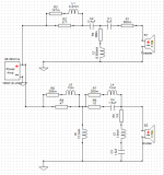
That's great! 🙂 Use the ground symbol so you dont' have to keep drawing lines back to (-) though. XSim will interpret everything attached to a ground as going to the same place. IT will visually clear up the schematic.
In the FR graph, import your full Tweet + Woofer (no crossover) graph.
USe that as your reference.
Compare it to your simulated output, and delay the woofer until the FR's match as precisely as possible.
Then take a look at Steve's (System7's) suggestions for crossovers, just to play around with them. Try them out in XSim and see if you like any of them.
Better to play for a while than attempt adjustments for now.
Erik
Double check the tweeter and woofer are both imported by plotting only one or the other in the FR chart. 🙂
Last 2 images in post above is tweeter+woofer without crossover so thats the reference then 🙂That's great! 🙂 Use the ground symbol so you dont' have to keep drawing lines back to (-) though. XSim will interpret everything attached to a ground as going to the same place. IT will visually clear up the schematic.
In the FR graph, import your full Tweet + Woofer (no crossover) graph.
USe that as your reference.
Compare it to your simulated output, and delay the woofer until the FR's match as precisely as possible.
Then take a look at Steve's (System7's) suggestions for crossovers, just to play around with them. Try them out in XSim and see if you like any of them.
Better to play for a while than attempt adjustments for now.
Erik
Aha, so ill get a FRD file of the full system without crossover aswell and display both? Will do!
I can play around with them but its kind of hard for me to know if i like any particular one, im aware of that the curve should be as straight as possible but thats about it 🙂
Checked and they are both there 🙂Double check the tweeter and woofer are both imported by plotting only one or the other in the FR chart. 🙂
Thanks for the input!Sometimes I read a thread and think you guys are making it more difficult than it is!
This is a foam surround polycone which is doubtless quite well-behaved on it's own. Just like the old Vifa P17WJ.
Vifa 2-Way Loudspeaker System
And a classic old peerless CT62H cone tweeter. Marshall Leach's circuit will probably do about the right things, though you can do more. 6" polycone is an easy speaker. Possibly 2.5kHz crossover. I'd spray the baffle black too.
I will draw this circuit in Xsim to see what results we get 🙂
Thanks for the input!
I will draw this circuit in Xsim to see what results we get 🙂
Yep, as soon as you do System7's suggestions will be great things to explore. He knows his stuff when it comes to crossovers and old british speakers. 🙂
Definitely a friendship to cultivate.
Best,
Erik
Yea, he seems to know what he is talking about 🙂 I actually tested the circuit he showed 69 in # but then i realized i had to do the delay first..
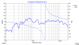
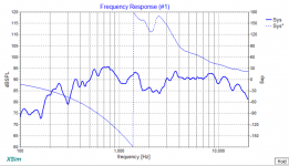
I've got the full no crossover graph into RF now, without delay:

When i adjust this, what is my goal? Some specific part i should aim on getting down? Ive tried both positive and negative delay and it's not getting that much better than without delay.
I also attached the RFD files(renamed to .txt)
I've got the full no crossover graph into RF now, without delay:
When i adjust this, what is my goal? Some specific part i should aim on getting down? Ive tried both positive and negative delay and it's not getting that much better than without delay.
I also attached the RFD files(renamed to .txt)
Attachments
Last edited:


Sultanen you are very busy with your sims! 🙂
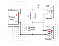
Can I suggest a couple of circuits to try? These use polycones:
Heybrook HB2 simplified:
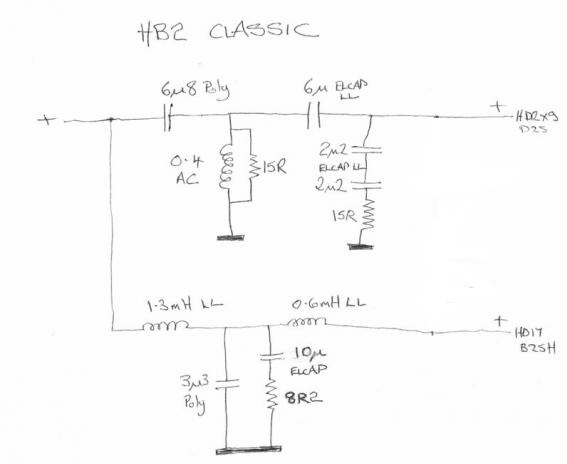
KEF Cadenza, for which you should flip the tweeter polarity IMO, this being an 8" bass circuit, yours being 6" bass:
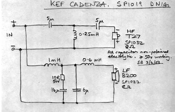
You'll need to attenuate the tweeter, of course.
Can I suggest a couple of circuits to try? These use polycones:
Heybrook HB2 simplified:
KEF Cadenza, for which you should flip the tweeter polarity IMO, this being an 8" bass circuit, yours being 6" bass:
You'll need to attenuate the tweeter, of course.
Woah. 🙂
Do the delay calculations first. You are looking for the best match of FR. Try changing the woofer delay about 1/4" at a time first. You can estimate the delay by measuring the horizontal distance between the back of the tweeter to the back of the woofer. It's probably at least an inch. You'll see the FR suddenly snap into place assuming you measured correctly, without the cap, and without moving the microphone, and microphone on tweeter axis.
Best,
Erik
Cap removed, mic on tripod and adjusted measured to be in center of tweeter.Woah. 🙂
Do the delay calculations first. You are looking for the best match of FR. Try changing the woofer delay about 1/4" at a time first. You can estimate the delay by measuring the horizontal distance between the back of the tweeter to the back of the woofer. It's probably at least an inch. You'll see the FR suddenly snap into place assuming you measured correctly, without the cap, and without moving the microphone, and microphone on tweeter axis.
Best,
Erik
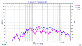
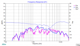
I did the measurements of the drivers and i got about a 6.5cm or 2.56in diff from the back of the tweeter to the back of the woofer. When i add that into Xsim i get:
2.56in:
2.88in:
3.23in:
0.87in:
I think 3.23in looks like the best match?
Another question, how do you incorporate the delay into the crossover? 🙂
Attachments
Last edited:
Thanks alot for the circuits! Will try some simulations on them as soon as we have decided on the delay =)Sultanen you are very busy with your sims! 🙂
Can I suggest a couple of circuits to try? These use polycones:
Heybrook HB2 simplified:
KEF Cadenza, for which you should flip the tweeter polarity IMO, this being an 8" bass circuit, yours being 6" bass:
You'll need to attenuate the tweeter, of course.
In the meantime, i have to ask, how to one "attenuate the tweeter"? 🙂
Yep! 🙂 I mean, once you are close, you can try small changes, like 0.1" at a time. 🙂
Now, play with Steve's stuff for a while, soak up his knowledge. Later we can talk about optimizing your drivers.
It may help you too if you use some of the Circuit blocks in XSim. The L Pad is a good one to start with, it's convenient and will help you set the tweeter level.
You can replace what you see in Steve's notes with the block instead of individual resistors.
Best,
Erik
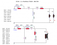
Ooh, I've just realised I've seen Mr. Troels Gravesen, no less, doing stuff with the Peerless CT62H!
Philips 9710/
This is always a help to get some confirmation of the right approach.
He's using a third order filter on the (paralleled) cone tweeters, as I often do. Here 2.5kHz crossover.
You halve the capacitors and double the inductors for a single tweeter. The resistor in front of the filter adjusts level. I always put 22R shunt after the filter too.
Attachments
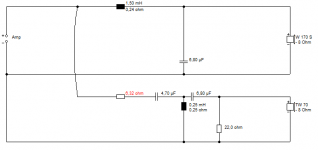
It must be getting late in Sweden, but I've dug up some woofer data:
Imbedanssi 8 ohms
Taajuusvaste 48-4,800 Hz
Fs: 47.5 Hz
SPL: 89 dB 2.83V/1m
Vas: .20,7
Qms: 1.63
Qes: 0.42
Qts: 0.34
Xmax: 4mm
Paino: 1.5kg
And an Le of 0.8mH we knew already. Which is voicecoil inductance. And that is a reflex driver with a smallish xmax.
I've been looking at a circuit like below, which seems to do the right things. Now do bear in mind I'm using different, albeit similar, drivers.
Attachments
Thanks for that link!Ooh, I've just realised I've seen Mr. Troels Gravesen, no less, doing stuff with the Peerless CT62H!
Philips 9710/
This is always a help to get some confirmation of the right approach.
He's using a third order filter on the (paralleled) cone tweeters, as I often do. Here 2.5kHz crossover.
You halve the capacitors and double the inductors for a single tweeter. The resistor in front of the filter adjusts level. I always put 22R shunt after the filter too.
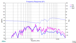
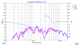
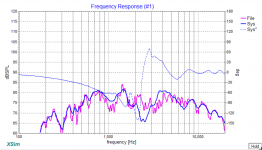
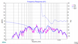
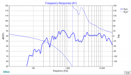
I have simulated the previous circuits but haven't posted the results yet. This however looks like the best one yet 🙂 Its starts to look straighter now! I changed it as you instructed for single tweeter.
without Woofer delay
3.23in delay:
3.23in delay but min freq 20 instead of 100:
Getting there? =)
I still dont have any bass at all though? =/
Attachments
Last edited:
I'd suggest show the bass separately, and change the range on XSim so we can see down to 20 Hz. 🙂 It will help.
Remember early on I suggested the first thing to do was to flatten the bass from the 40Hz level or so? 🙂
- Status
- Not open for further replies.
- Home
- Loudspeakers
- Multi-Way
- 2 Way speakers - Suggestions on improvements?