hello gentlemen
I have a question guys I'm trying to figure how much bias adjustment I need to have for 4 pairs using the AX-14 circuit IPS and I only adding 3 more pairs and I'm thinking that bias would be different, I place a volt meter reading on one of the emitter resistors to read mV there what would be the correct adjustment for 4 pairs output using 65V DC supply ? I mean close enough approximation 🙂
I have a question guys I'm trying to figure how much bias adjustment I need to have for 4 pairs using the AX-14 circuit IPS and I only adding 3 more pairs and I'm thinking that bias would be different, I place a volt meter reading on one of the emitter resistors to read mV there what would be the correct adjustment for 4 pairs output using 65V DC supply ? I mean close enough approximation 🙂
Attachments
hello gentlemen
I have a question guys I'm trying to figure how much bias adjustment I need to have for 4 pairs using the AX-14 circuit IPS and I only adding 3 more pairs and I'm thinking that bias would be different, I place a volt meter reading on one of the emitter resistors to read mV there what would be the correct adjustment for 4 pairs output using 65V DC supply ? I mean close enough approximation 🙂
You must use triple emiter folower to drive 4 pairs like in AX20 or BX20.
Regards
You must use triple emiter folower to drive 4 pairs like in AX20 or BX20.
Regards
oh man 🙁 now I have to re-done some areas of the PCB is ok I can do that 🙂
thanks mister Mile
Best Regards
Juan
oh man 🙁 now I have to re-done some areas of the PCB is ok I can do that 🙂
thanks mister Mile
Best Regards
Juan
Only change one output pair to drive 3 output pairs like in BX20
Regards
Only change one output pair to drive 3 output pairs like in BX20
Regards
ok BX20 ? I have not see, what post number mister Mile ?
Regards
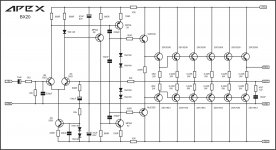
bx20
oh I see I think I can give the layout that option on the PCB I will figure that out later I have to " brainstorm " for a while 😛 but, the good think is that on simulation as it is I think it does responds really well 🙂 I'm not searching to get lot of power just a bit more
Attachments

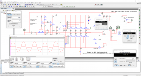

Dragan made changes and simulation of FX8CD.
So the FX8 in this version can use cost effective vertical hexFETS?
That amp has 3 extra transistors so I'm not so sure how "cost effective" that is. It should probably be called an FX11.
I did a quick layout for the FX8CD. Can you please check it?
Thanks, Terry
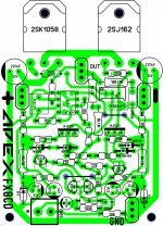
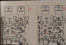
base MJE350 no conected
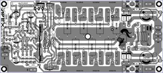
Layout for Apex BX20. I'll make one more version of BX20.
Dear sonal would. U share bx20 pcb in sprint/pdf form
base MJE350 no conected
Thanks for that. I moved the MJE50 at the last minute so it would align with the MJE40 just in case they needed a common heatsink. I re-connected the diodes to the collector instead of the base. I think I have it right now.
Thanks again, Terry
Attachments

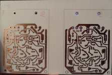
OK I etched a pair. Tomorrow I'll try to get them populated.
Hmm, I just noticed I forgot to change the label on the foil side. I'll take care of that now. 😉
Nice pcb, but you must replace resistors value (270R with 100R...) Use values from Dragans simulated schematic of FX11 for input stage, output stage with 2SJ/2SK is ok.
10pF misisng on your pcb...
Regards
Last edited:
OK I etched a pair. Tomorrow I'll try to get them populated.
Hmm, I just noticed I forgot to change the label on the foil side. I'll take care of that now. 😉
IRFP and 2SK/SJ have different pin outs. which one have you considered while making layout?
- Home
- Amplifiers
- Solid State
- 100W Ultimate Fidelity Amplifier