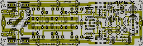
sprint layout PCB AX11TEF not tested
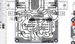
Nice layout!. It is indeed possible (with few mods) to separate i/p ground and power gnd on your layout. nice🙂. But don't know if that is required as most APEX layouts recently seem to have them combined.
reg
Prasi
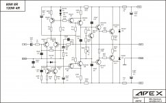
Layout for Apex BX20. I'll make one more version of BX20.
Nice pcb, thanks.
Regards
Thanks. Any recommended alternatives as these are kind of hard to get from a regular supplier like Mouser and Digikey. They seem to be availnale on eBay only.
Dont buy the latfets off the bay. You might end up getting the "TOSHIBA" ones😀.
sprint layout PCB AX11TEF not tested
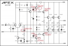
Nice pcb, thanks. You have wrong notification for outputs 2SA1943 instead 2SA1940 and 10R/1W work with 1mW disipation so you don't need 1W resistors, 0,25W will be ok.
Regards

Nice pcb, thanks. You have wrong notification for outputs 2SA1943 instead 2SA1940 and 10R/1W work with 1mW disipation so you don't need 1W resistors, 0,25W will be ok.
Regards
Done. Thanks
"to separate i/p ground and power gnd on your layout"
Done. Thanks
Attachments
Hi Mile,
I can make these modification?
thanks
Yes it is ok.
Regards
No you can't replace Lateral mosfet with vertical mosfet. You can use other lateral mosfets from Exicon or Semelab.
I am getting confusing info here because I am seeing that IRFP240/9240 are lateral MOSFET's. They are actually used in many Pass class A amps.
Where does it say they are vertical topology?
I am getting confusing info here because I am seeing that IRFP240/9240 are lateral MOSFET's. They are actually used in many Pass class A amps.
Where does it say they are vertical topology?
IRFP240/9240 are not Lateral mos but vertical ones....
Marc
Ok I see it now. The vertical hexfets can be used for audio but need a very high bias current bordering on heater class A operation to be linear.
Nice pcb, thanks. You have wrong notification for outputs 2SA1943 instead 2SA1940 and 10R/1W work with 1mW disipation so you don't need 1W resistors, 0,25W will be ok.
Regards
sir, what is the rms power output in 4 /2ohoms speaker if I use 55 0 55v/1000va transformer in apex bx20 amps?
sir, what is the rms power output in 4 /2ohoms speaker if I use 55 0 55v/1000va transformer in apex bx20 amps?
400W/4R 650W/2R

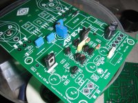
this might be a silly question but but anyway here we go, my question is does Q8 and Q9 need to be thermally couple together or is not really needed ?
No need but you can thermally couple Q1-Q2, Q4-Q5 and Q8-Q9.
Last edited:
Hi,
Am no expert Jaun,But I did try both the options and definitely there is an advantage in coupling them thermally !!
Without coupling I got a DC offset of -20-40mv and after coupling I got -2mv !!
Regards.
my question is does Q8 and Q9 need to be thermally couple together
Am no expert Jaun,But I did try both the options and definitely there is an advantage in coupling them thermally !!
Without coupling I got a DC offset of -20-40mv and after coupling I got -2mv !!
Regards.
Hi,
Am no expert Jaun,But I did try both the options and definitely there is an advantage in coupling them thermally !!
Without coupling I got a DC offset of -20-40mv and after coupling I got -2mv !!
Regards.
thank for the replay I will try this way thank again 🙂 uhm -2mv amazing indeed !
Attachments
Hi,
No need to thank as I/we have to thank you for all the help and support that have providing/ed !
!
Am sorry but there was a small mistake in my post above,When I say thermal coupling,I just put both on a same heatsink (as opposed to attaching both face to face) Q8&9 that is,Where as Q1-2,4-5,6-7 I coupled it treditionally (put them face to face,It was mother of all pain as the layout is not designed for the same,In the bargain broke legs multiple devices 😛). Q6-7 might not yeild any postive result but I still went for it just cause..............
If you match them then almost 0 Dc offset is possible,I myself without matching got almost -0.9mv at one point before breaking the legs !
!
Hope this helps and I have not caused any problems with my above post.
Regards.
thank for the replay I will try this way thank again uhm -2mv amazing indeed !
No need to thank as I/we have to thank you for all the help and support that have providing/ed
!Am sorry but there was a small mistake in my post above,When I say thermal coupling,I just put both on a same heatsink (as opposed to attaching both face to face) Q8&9 that is,Where as Q1-2,4-5,6-7 I coupled it treditionally (put them face to face,It was mother of all pain as the layout is not designed for the same,In the bargain broke legs multiple devices 😛). Q6-7 might not yeild any postive result but I still went for it just cause..............
If you match them then almost 0 Dc offset is possible,I myself without matching got almost -0.9mv at one point before breaking the legs
!Hope this helps and I have not caused any problems with my above post.
Regards.
Last edited:
Greetings mr.apex sir can i use bx20 amp for public address
Yes but protect must be add.
- Home
- Amplifiers
- Solid State
- 100W Ultimate Fidelity Amplifier