Yes if PRO pin is connected to emiter of NPN output transistors in positive rail.
Regards
Thank you so much sir Mile for answering all my queries regarding this brilliant creation of yours. I love to follow this thread every now and then...😉😉
God bless and more power...
vinski80
can the circuit at Post 5656 be used with specific power amplifier, Or Protect input can be connected to output terminal of any power amplifier.
can the circuit at Post 5656 be used with specific power amplifier, Or Protect input can be connected to output terminal of any power amplifier.
Protect from post 5656 can be use with any amplifier.
I make AX16 simulation.
I modified it and made a PCB layout.
If the value of the components of the schematic is different from simulation file, the simulation is the correct one.
Attachments
I modified it and made a PCB layout.
If the value of the components of the schematic is different from simulation file, the simulation is the correct one.
Nice work, thank you.
Regards
I modified it and made a PCB layout.
If the value of the components of the schematic is different from simulation file, the simulation is the correct one.
Hi Bimo,
Is this a Sprint file? Would you share it? If not. could you attach a mirror of the silk please? I would be willing to build this.
Blessings, Terry
I modified it and made a PCB layout.
If the value of the components of the schematic is different from simulation file, the simulation is the correct one.
The way you have connected R9 = 200 Ohm is not a good idea (your solution for OFFSET adjustment is not very efficiency). Please think again. 🙂
Hi Bimo,
Is this a Sprint file? Would you share it? If not. could you attach a mirror of the silk please? I would be willing to build this.
Blessings, Terry
Hi Terry,
attached is the mirror silk. I have cleaned dark mount holes a bit. design is in eagle and I know the export in pdf is a bit ugly. Pl let me know if this is what u needed.
reg
prasi
Attachments
Last edited:
Hi Bimo,
Is this a Sprint file? Would you share it? If not. could you attach a mirror of the silk please? I would be willing to build this.
Blessings, Terry
No, it is eagle file.
The way you have connected R9 = 200 Ohm is not a good idea (your solution for OFFSET adjustment is not very efficiency). Please think again. 🙂
Do you think it must connect to emitter of the LTP (paralel with R5 and R10)?
I modified it and made a PCB layout.
If the value of the components of the schematic is different from simulation file, the simulation is the correct one.
I revise the PCB layout. I change C9 dan r18 position.
Attachments
That doesn't make sense. Can you post the new schematic?
Shematic is same as http://www.diyaudio.com/forums/solid-state/164093-100w-ultimate-fidelity-amplifier-569.html#post4544670
I change the R and C position because R connection to the transistor have high impedance, and it might interference from output signal.
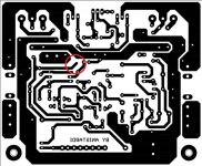
There is a trace that is not connected. Is that by design?
Yes, it used for guarding the high impedance node from output signal.
Is someone who work drawing a pcb for this new schematic?PRO portion is add, but will work only with AX16, HV23...
Yes, it's much better, primarily because of R9 cursor in the event of interruption (in time may compromise the wiper resistance) does not cause the emergence of the offset voltage in the output stage.Do you think it must connect to emitter of the LTP (paralel with R5 and R10)?
Yes, it's much better, primarily because of R9 cursor in the event of interruption (in time may compromise the wiper resistance) does not cause the emergence of the offset voltage in the output stage.
OK, I revised it.
Attachments
- Home
- Amplifiers
- Solid State
- 100W Ultimate Fidelity Amplifier