Hello Mr.apexaudio
i did build your AX-14 ... it's working just have two problems :
1- i cant measure the 30mv bias on both of the emitter resistors ... however the 2SC5200/2SA1943 affected by the bias trimer and get very hot and very cool but no change in the sound.
2- the output by anyway not more that 40w/8ohm i'm applying +ve and -ve 40VDC supply.
and suggestions??!!
My boards aren't working. I built a spice file but I can't get it working either. Maybe one of you Ltspice gurus can fix it so I can use it to troubleshoot.
Thanks, Terry
Thanks, Terry
Attachments
Last edited:
It shows 25V output in the ltspice sim.
source of 2sk117 jfet is at 2V, see posted .op gotta go now
Yeah, I know the voltages are all wrong. I'm attaching an updated file. It doesn't work either. I changed the OP and added a model for the 2SK117.
Anyone?
Attachments
Terry, your #5043 schematic has the op-amp input polarity wrong.
Yes I checked the data sheet and saw that I had the wrong part. For the updated file I changed it to LT1022 which should be closer to the TL071. THe polarity is correct too. It still doesn't run right.
Hi Mile,
Did you try the revised asc file?
Thanks, Terry
Hi Terry, I'm very sorry. Obviously there is a mistake in the layout. Unfortunately I could not find the error now up. I'll keep looking and also follow the advice by Mile.
regards
Olaf
regards
Olaf
Hi Olaf,
I went over your layout with a highlighter and found no errors. I still can't get the spice file to work. Mile says it works in Multisim but I don't have that program so I can't test it there. I do think the input needs the resistor that AndrewT suggested. All the amps I have built have that resistor. Most have an input cap as well that this one doesn't have. I'm glad we started with this one before jumping into the tube version. If this won't work, the tube probably won't either. I'm sure we'll get it working and probably learn something along the way.
Blessings, Terry
Hi Terry,
I just open the asc file, and for first seen the opamp in the DC servo is wrong connected. The AC feedback is positive...
Sajti
I just open the asc file, and for first seen the opamp in the DC servo is wrong connected. The AC feedback is positive...
Sajti
Did you open the revised file from post 5045? If that one is wrong can you fix it and see if it will run properly?
Edit ; I just checked and the opamp in mile's schematic is tied to the negative pin. Please check my schematic against Mile's.
Thanks, Terry
Edit ; I just checked and the opamp in mile's schematic is tied to the negative pin. Please check my schematic against Mile's.
Thanks, Terry
Last edited:
Did you open the revised file from post 5045? If that one is wrong can you fix it and see if it will run properly?
Edit ; I just checked and the opamp in mile's schematic is tied to the negative pin. Please check my schematic against Mile's.
Thanks, Terry
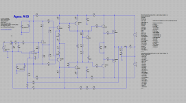
This picture coming from the revised schematic. C2 is wrong for sure. I had no time to play with the schematic yet...
Sajti
Attachments

Look at the schematic in post 5025.C2 looks the same.
That is true, but the inverting, and non-inverting input of the opamp is opposite.
I just played a bit, and You can see my revision attached.
Sajti
Attachments
Hi Terry, that's the right spirit! 🙂Hi Olaf,
I went over your layout with a highlighter and found no errors. I still can't get the spice file to work. Mile says it works in Multisim but I don't have that program so I can't test it there. I do think the input needs the resistor that AndrewT suggested. All the amps I have built have that resistor. Most have an input cap as well that this one doesn't have. I'm glad we started with this one before jumping into the tube version. If this won't work, the tube probably won't either. I'm sure we'll get it working and probably learn something along the way.
Blessings, Terry
Greetings Olaf
I think you are referring to a resistor between Signal Ground and Power Ground?.................. I do think the input needs the resistor that AndrewT suggested. All the amps I have built have that resistor. Most have an input cap as well that this one doesn't have................
If so, then it is only necessary when you have a multi-channel power amplifier.
If you are testing a Mono-Block, then that loop current reducing resistance has no purpose. There is no loop that needs the current to be attenuated.
The basic sch is correct for a mono-block.
The Signal Ground to Power Ground link is shown just below V3 at the input.
It is this link that would need a resistance value when building a two channel, or multi-channel, power amplifier. And for a faulty source, this resistance needs a pair of safety inverse parallel diodes to take Fault Current to Chassis and thence to PE.
Last edited:
I think you are referring to a resistor between Signal Ground and Power Ground?
If so, then it is only necessary when you have a multi-channel power amplifier.
If you are testing a Mono-Block, then that loop current reducing resistance has no purpose. There is no loop that needs the current to be attenuated.
The basic sch is correct for a mono-block.
The Signal Ground to Power Ground link is shown just below V3 at the input.
It is this link that would need a resistance value when building a two channel, or multi-channel, power amplifier. And for a faulty source, this resistance needs a pair of safety inverse parallel diodes to take Fault Current to Chassis and thence to PE.
No, I'm talking about the 1k resistor ahead of the 330p cap. It's not there in Mile's schematic. I added it to the spice file. It's the one that Olaf added with an SMD. The ground lift resistor you refer to is missing but you still need to run an extra wire from input ground to star. Kind of a hassle when you use a pin header plug like I did.
Did the file run properly after the changes? I am not at my computer so I can't test it right now.That is true, but the inverting, and non-inverting input of the opamp is opposite.
I just played a bit, and You can see my revision attached.
Sajti
Blessings, Terry
Last edited:
Did the file run properly after the changes? I am not at my computer so I can't test it right now.
Blessings, Terry
Yes, it was OK then. I have to change some part number too, as I had no modell for them in my office computer. But the main thing to change is the connection of the DC servo.
Sajti
Yes, it was OK then. I have to change some part number too, as I had no modell for them in my office computer. But the main thing to change is the connection of the DC servo.
Sajti
I guess we may need to cut some traces on the the PCB?
- Home
- Amplifiers
- Solid State
- 100W Ultimate Fidelity Amplifier