I guess we may need to cut some traces on the the PCB?
Maybe Yes, but I don't want to force You to change. Maybe Apex can help with the existing schematic.
Sajti
I just checked and the original schematic has the NFB going to the - input on the servo so the layout is correct to Mile's schematic. It is just the spice opamp that has the pins reversed. I changed the circuit to match yours but it still doesn't run properly. It shows 8V offset. Maybe one of my models isn't correct. I had to use the IRFP240/9240 from the Cordell Models.txt and I got the 2SK117 model from a thread here on the forum. I you use the Cordell Models file I attached, the file should run for you at work. I added the three models not there to the spice file.
Thanks, Terry
Thanks, Terry
Hi Terry,
I also changed the connection of the output of the DC servo, because the original has not enought output voltage to compensate the offset. I guess that connctin the output to the source of the JFET is generally bad idea.
Sajti
I also changed the connection of the output of the DC servo, because the original has not enought output voltage to compensate the offset. I guess that connctin the output to the source of the JFET is generally bad idea.
Sajti
Hi Terry,
I also changed the connection of the output of the DC servo, because the original has not enought output voltage to compensate the offset. I guess that connctin the output to the source of the JFET is generally bad idea.
Sajti
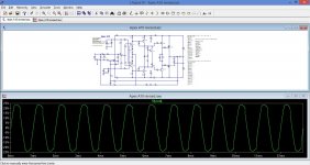
Awww, I didn't notice that. I changed that and now the offset is gone but a pretty ugly sine wave. See attached. At least I have some voltage references now to use to trouble shoot the boards.
Blessings, Terry
Attachments
Awww, I didn't notice that. I changed that and now the offset is gone but a pretty ugly sine wave. See attached. At least I have some voltage references now to use to trouble shoot the boards.
Blessings, Terry
Check/set the bias current on the output stage. There was no any bias set in Your simulation.
Sajti
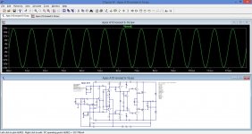
It was my models for the MPSA42/92. I replaced those with 2N5401c/5551c and the sine wave is good now. I had to change R23 to 68R as the gain was too high. Trimmer is at 660R to get about 100mA bias. I have 4V on the base of the MOSFETs. Is that normal?
Getting closer now. Should be good enough to use for troubleshooting.
Thanks, Terry
Getting closer now. Should be good enough to use for troubleshooting.
Thanks, Terry
Attachments
OK, here's an update. I lifted the 8k2 and attached it to the gate of the jfet. That solved the offset issue. The amp can be biased now and it will pass a signal but square waves look ugly and sine wave distort at about 5vac output. Something is still not right. Also the bias goes very high with only a little output. I forgot about the high gain. I will try reducing that and test again.
Blessings, Terry
Blessings, Terry
Hi, I have done nearly the same. I followed Miles advice and replaced the 8k2 with Pot and adjusted the offset near 0. I measured the Pot and replaced 8k2 to 2k2. Now the offset is 2mV and signal is there. But sine looks not good. I could not measure more things.
I can't work longer this evening. But there is hope 😀
regards Olaf
I can't work longer this evening. But there is hope 😀
regards Olaf
Last edited:
I misspoke earlier. The issue was with my sine generator. The square and sine waves look beautiful. The only issue I have is with one board. I plays perfectly with the sine wave generator plugged into the input or with the input shorted, but as soon as I plug in the CD player it starts pulsing. The other board doesn't do this so now I have to hunt down a ghost.
Olaf, have you tried moving the 8k2 over from the source to the gate of the jfet? It completely solved the offset issue for me. It was easy to do. Just unsolder the leg of the 8k2 farthest from the input and spin it around and solder it to the leg of the 100R resistor closest to the jfet. I may drill a hole later and solder it under the board.
Blessings, Terry
Hi Terry, I was in a hurry. So I'm not sure that all connections were correct. Maybe the signal's perfectly fine when I do everything properly.
It does not seem right to me to put the outcome of the servo directly to the input of the amplifier. But that should decide Mile as a designer.
As soon as I find time, I test all over again.
I'm still on the road, Greetings Olaf
It does not seem right to me to put the outcome of the servo directly to the input of the amplifier. But that should decide Mile as a designer.
As soon as I find time, I test all over again.
I'm still on the road, Greetings Olaf
I misspoke earlier. The issue was with my sine generator. The square and sine waves look beautiful. The only issue I have is with one board. I plays perfectly with the sine wave generator plugged into the input or with the input shorted, but as soon as I plug in the CD player it starts pulsing. The other board doesn't do this so now I have to hunt down a ghost.
Olaf, have you tried moving the 8k2 over from the source to the gate of the jfet? It completely solved the offset issue for me. It was easy to do. Just unsolder the leg of the 8k2 farthest from the input and spin it around and solder it to the leg of the 100R resistor closest to the jfet. I may drill a hole later and solder it under the board.
Blessings, Terry
It is a fast solution. However it reduce the input impedance of the amplifier. I would increase the value of it. You will find some more difference, if You check my schematic carefully.
Sajti
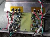
I may try reducing that to see what difference it might make. I found the issue with the ghost. I had changed the 47R to 75R on one board. After I changed the other board to 75R the pulsing is gone and both boards play perfectly. On my boards at least, 47R results on too much gain. I have the bias set to 60mA at the rail and it sounds great. I'm not pushing it hard so maybe higher would be better at louder volumes. There is no visible crossover distortion on the scope.
I installed 1k2 at the input because that is what I had handy. The caps is still 100p. I also installed a 1W 4R7 SMD under the board to connect the signal ground to the power ground. Probably in a case it would be better to run a separate ground wire to the star but on my bench it is better for me to have that resistor in there so I don't have to worry about it.
I'll post up some scope shots in a while for those interested.
Blessings, Terry
Hi Project,
You are too kind. It is only due to the great advice I receive from the kind and knowledgeable folks on this forum.
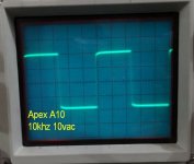
OK, these are the changes I have made based on advise given here.
Inserted 1k2 resistor between input and 100p cap
Added 4R7 ground lift resistor at signal ground.
Changed 47R to 75R to reduce gain.
Moved 8K2 from JFET source to gate.
I might install an input cap. I do see some offset voltage variances when testing with my sine wave generator. Nothing the servo can't correct.
Sounds lovely.
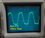
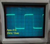
I'm using a small PSU right now. Only 300VA so it sags a little. I'm not sure how high I can go on the rails for this little amp. Can probably get more output with a stiffer supply but this is plenty for normal listening.
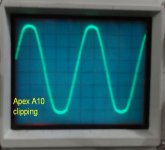
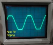
The amps clips softly. Very rounded top and bottom.
I'm attaching some scope shots for your viewing pleasure.
Blessings, Terry
You are too kind. It is only due to the great advice I receive from the kind and knowledgeable folks on this forum.
OK, these are the changes I have made based on advise given here.
Inserted 1k2 resistor between input and 100p cap
Added 4R7 ground lift resistor at signal ground.
Changed 47R to 75R to reduce gain.
Moved 8K2 from JFET source to gate.
I might install an input cap. I do see some offset voltage variances when testing with my sine wave generator. Nothing the servo can't correct.
Sounds lovely.
I'm using a small PSU right now. Only 300VA so it sags a little. I'm not sure how high I can go on the rails for this little amp. Can probably get more output with a stiffer supply but this is plenty for normal listening.
The amps clips softly. Very rounded top and bottom.
I'm attaching some scope shots for your viewing pleasure.
Blessings, Terry
Attachments
-
 Apex A10 150khz.jpg45.3 KB · Views: 234
 -
 Apex A10 100khz.jpg47.2 KB · Views: 245
 -
 Apex A10 50khz.jpg45.3 KB · Views: 247
 -
 Apex A10 20khz.jpg45.2 KB · Views: 267
 -
 Apex A10 10khz.jpg45.5 KB · Views: 1,026
 -
 A10 clipping.jpg45.2 KB · Views: 1,051
 -
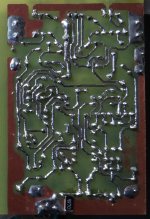 Apex asbuilt foil.jpg400.7 KB · Views: 1,123
 -
 Apex A10 singing.jpg129.9 KB · Views: 1,182
 -
 8K2 relocation.jpg409.7 KB · Views: 1,301
 -
 Apex A10 1khz.jpg46.2 KB · Views: 224
Last edited:
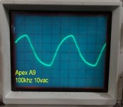
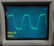
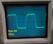
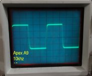
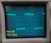
Hi Terry,great work as always. Can you post shots from A9? How does A10 sound compared to A9?
Olafk can you post sprint layout file for A10?
Olafk can you post sprint layout file for A10?
Last edited:
Yes, I should be able to show some scope shots tomorrow. These amps all sound pretty much the same. Clear, musical with good solid bass. You don't really hear much difference until you play them loud. The amps with multiple pairs of outputs will start to outshine the lower powered units when pushed. But at normal listening levels these smaller amps are sweet. After initial testing I hooked up this 200W +-25V SMPS. Amazing results. The SMPS hold a steady 25.5V even under high load. I tested against a PMI VSSA and a Symasym on my A/B system and it held its own very well. This would make a great, inexpensive, compact amplifier. Highly recommend it.
Blessings, Terry
Blessings, Terry
Read Leach.I may try reducing that to see what difference it might make. I found the issue with the ghost. I had changed the 47R to 75R on one board. After I changed the other board to 75R the pulsing is gone and both boards play perfectly. On my boards at least, 47R results on too much gain. I have the bias set to 60mA at the rail and it sounds great. I'm not pushing it hard so maybe higher would be better at louder volumes. There is no visible crossover distortion on the scope.
I installed 1k2 at the input because that is what I had handy. The caps is still 100p. I also installed a 1W 4R7 SMD under the board to connect the signal ground to the power ground. Probably in a case it would be better to run a separate ground wire to the star but on my bench it is better for me to have that resistor in there so I don't have to worry about it.
I'll post up some scope shots in a while for those interested.
Blessings, Terry
He too puts a 10r resistor in the Signal Ground to Power Ground.
It acts as the reference voltage so that Output and Input are referenced to the same voltages.
He also goes on to describe the long wire connection from Input to Chassis and describes this as HIGH impedance but since the 10r is on the PCB with short traces it is the LOW impedance connection.
Keep the SMD resistor on the PCB using the shortest trace length between the Signal Ground and the Power Ground.
try not to use this phrase.Added 4R7 ground lift resistor at signal ground.
The purpose of the resistor in a two channel or multi-channel amplifier is to increase the impedance in the signal routing to attenuate the loop current that is interfering with the signal current/voltage.
"Loop current reducing resistor" would do, if you don't like typing attenuating.
Is there a better name that does not imply "LIFTING the Ground" ?
Terry,post updated schematic,better way🙂Hi Project,
You are too kind. It is only due to the great advice I receive from the kind and knowledgeable folks on this forum.
OK, these are the changes I have made based on advise given here.
Inserted 1k2 resistor between input and 100p cap
Added 4R7 ground lift resistor at signal ground.
Changed 47R to 75R to reduce gain.
Moved 8K2 from JFET source to gate.
I might install an input cap. I do see some offset voltage variances when testing with my sine wave generator. Nothing the servo can't correct.
Sounds lovely.
I'm using a small PSU right now. Only 300VA so it sags a little. I'm not sure how high I can go on the rails for this little amp. Can probably get more output with a stiffer supply but this is plenty for normal listening.
The amps clips softly. Very rounded top and bottom.
I'm attaching some scope shots for your viewing pleasure.
Blessings, Terry

- Home
- Amplifiers
- Solid State
- 100W Ultimate Fidelity Amplifier