what is happening to the LF response during your tests.
The bass and lower mid is rolled off.
Is it the AC coupling of the scope, or a DC blocking cap somewhere, or is ti inside the amplifier?
Where has the HF gone in the tests?
Compare the 1kHz and 100kHz squarewaves for the two amplifiers.
The bass and lower mid is rolled off.
Is it the AC coupling of the scope, or a DC blocking cap somewhere, or is ti inside the amplifier?
Where has the HF gone in the tests?
Compare the 1kHz and 100kHz squarewaves for the two amplifiers.
I'm just t posting what I see. I'm not sure why the A9 is showing this. I'm going to try a different opamp and see if it improves.
I did more testing and get the same results. I tried the OPA2134 but it over drives the amp. Maybe with some changes it would work but not as is. The TL072 works the best. I can't say what is causing the roll-off but both channels do the same thing. In spite of this the amp has a pleasant sound.
I did more testing and get the same results. I tried the OPA2134 but it over drives the amp. Maybe with some changes it would work but not as is. The TL072 works the best. I can't say what is causing the roll-off but both channels do the same thing. In spite of this the amp has a pleasant sound.
thanks for the shots Terry. problem with opa2134? i think that Apex audio stated that it could be used. Soon i will finish my board...
Attachments
Last edited:
thanks for the shots Terry. problem with opa2134? i think that Apex audio stated that it could be used. Soon i will finish my board...
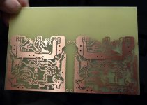
You inspired me. I thought I had built that layout but I dug through all the amps and I don't have one so I etched a pair and will try to get them populated tomorrow. Hopefully this one will measure better.
Blessings, Terry
Attachments
...............Is it the AC coupling of the scope, or a DC blocking cap somewhere, or is it inside the amplifier?................note correct spelling of "it"
There are three potential causes for the two amps to measure so differently.I did more testing and get the same results. I tried the OPA2134 ................. I can't say what is causing the roll-off .................
You need to check your test method. Could the way you are setting the scope switches or probe impedance be affecting the two amplifiers differently? Eliminate that first.
Check how the signal gets into the amplifier. Could you have some filters in the route that you had ignored because you thought that was unimportant?
Prove to yourself there are no inadvertent filters.
Then you can look at why the two amplifiers behave so differently.
You inspired me. I thought I had built that layout but I dug through all the amps and I don't have one so I etched a pair and will try to get them populated tomorrow. Hopefully this one will measure better.
Blessings, Terry
thats nice. post some scope shots when you are done and try opa2134 as well.
There are three potential causes for the two amps to measure so differently.
You need to check your test method. Could the way you are setting the scope switches or probe impedance be affecting the two amplifiers differently? Eliminate that first.
Check how the signal gets into the amplifier. Could you have some filters in the route that you had ignored because you thought that was unimportant?
Prove to yourself there are no inadvertent filters.
Then you can look at why the two amplifiers behave so differently.
The two amps are hooked up exactly the same way. The scope is attached at the speaker terminals and the sine wave generator is fed into the input. They are different topologies. The A10 is CFA and the opamp only controls the offset. On the A9 the opamp is the front end. The A10 is clearly faster. I haven't hooked them up together on the A/B setup yet because I have been using the same PSU for both. I'm still in bed. I'll do some more testing later.
Blessings, Terry
Knowing what my amps look like I would say your A9 is severely band limited it you have proved to yourself that it is not a measurement error.
Now you should be trying to find where the band limiting is occurring. And it is at both ends, bass and treble. It's not just that the CFA is faster, it probably isn't..
Now you should be trying to find where the band limiting is occurring. And it is at both ends, bass and treble. It's not just that the CFA is faster, it probably isn't..
Hi, here are my last results:
At first I measured resistor (8k2 in schematics) with a potentiometer until the offset was 0. The pot I have replaced with 2k2. The sinus was then not symmetrical and signal looked inverted and with music was in the heights a scratching sound (see picture).
Then I tried Terrys variant. I also had to change the gain (47R -> 75R) because the gain fluctuated. The music sounded like the siren of the police 🙂
I will customize the layout with all the changes in the input and the new and old resistors from opamp to gate and source, so anyone can make his own experiments.
I'm not happy with it because I think that the original circuit with the correct dimensioning should also function properly. May be that Mile can give some hints what should be done.
regards Olaf
Attachments

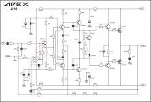

I guess Mile must be on holiday. I haven't seen him around lately. I don't know how it can work the way it is drawn. I can't get it to work in spice. I hope Mile chimes in to help us understand how this is supposed to work. I see you added the input cap. I've been trying to figure out how to add it to the boards.
Blessings, Terry
Blessings, Terry
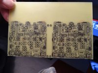
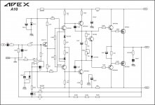
Hi, here is the layout file (Sprint 6.0) and corresponding schematic. If desired, I can make the pdf's.
regards Olaf
Hi Olaf,
just some remarks for the schematic:
You don't need the 2.2k resistor, if You use the 8.2k. I don't know any practical advantage to send the servo signal to the source of the input stage.
If You use my solution (servo resistor to the gate), and use coupling capacitor (which is mandatory for this version), You can increase the value of this resistor, even up to 1Meg. Using 8.2k to the gate will reduce the input impedance heavily...
IF You use 1M for the servo, You can reduce the value of the coupling capacitor, to 470nF-1uF range.
Sajti
Attachments
Last edited:
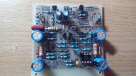
OK, so I finished the latest A9. Very strange little amp. I built both channels side by side using exactly the same parts. One channel plays beautiful crisp square waves and the other channel plays rounded waves similar to the pictures above. The other thing of interest is that I tried OPA2134. They work but they pull the zener down to 8V. One more thing. The channel with the pretty square waves has blown the outputs twice without warning. Something is not quite right. More testing tomorrow.
Blessings, Terry
Blessings, Terry
Attachments
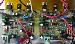
OK, so I finished the latest A9. Very strange little amp. I built both channels side by side using exactly the same parts. One channel plays beautiful crisp square waves and the other channel plays rounded waves similar to the pictures above. The other thing of interest is that I tried OPA2134. They work but they pull the zener down to 8V. One more thing. The channel with the pretty square waves has blown the outputs twice without warning. Something is not quite right. More testing tomorrow.
Blessings, Terry
Reduce the 2k2 2W resistors to 1.5k, it help to set the 15V for the OPA.
Sajti
Hi, I don't use both transistors. It is only for all they want to test both variants. They can choose what resistor they want to install.Hi Olaf,
just some remarks for the schematic:
You don't need the 2.2k resistor, if You use the 8.2k. I don't know any practical advantage to send the servo signal to the source of the input stage.
If You use my solution (servo resistor to the gate), and use coupling capacitor (which is mandatory for this version), You can increase the value of this resistor, even up to 1Meg. Using 8.2k to the gate will reduce the input impedance heavily...
IF You use 1M for the servo, You can reduce the value of the coupling capacitor, to 470nF-1uF range.
Sajti
What about changing the value of the resistor between opamp and gate? Why is the amplifier pumping or oscillating with higher gain?
regards Olaf
Last edited:
Olaf, your output is showing severe second harmonic distortion. This is typical of single ended as output approaches maximum.Hi, here are my last results:
At first I measured resistor (8k2 in schematics) with a potentiometer until the offset was 0. The pot I have replaced with 2k2. The sinus was then not symmetrical and signal looked inverted and with music was in the heights a scratching sound (see picture).
Then I tried Terrys variant. I also had to change the gain (47R -> 75R) because the gain fluctuated. The music sounded like the siren of the police 🙂
I will customize the layout with all the changes in the input and the new and old resistors from opamp to gate and source, so anyone can make his own experiments.
I'm not happy with it because I think that the original circuit with the correct dimensioning should also function properly. May be that Mile can give some hints what should be done.
regards Olaf
- Home
- Amplifiers
- Solid State
- 100W Ultimate Fidelity Amplifier