This sch looks nothing like post1.
Why are you posting in this Thread?
The Darlingtons have a VERY variable hFE. This depends critically on the output current and can vary from a very few thousand to approaching sixty thousand.
At low output current, the very high hFE will result in a tiny base current, so tiny you will not be able to measure it, (there is no base stopper resistor on any of the outputs. There is nowhere to monitor the base current).
You need to monitor the Vbias as well as Vre to see what effect turning the VR has.
Inserting the Vbemultiplier transistor back to front could result in a blow up. The VAS/Sink will apply a high voltage, approaching the rail to rail, if the Vbe multiplier impedes the VAS to Sink current flow. This will fully turn on the Darlingtons and they will probably blow up as well, if the mains fuse does not rupture quickly enough.
This is where using the Mains Bulb Tester for each power ON is so useful.
Last edited:
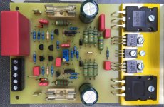
I bought a couple of boards of a forum member I finally sparked up and they have a fault. This is the DX14 with two pairs of darlingtons. TIP141 and TIP146.
Same in both so it looks like it may be an assembly problem, ie wrong component. I check all resistors and transistors and it looks in order. supply Voltage is +/- 45V.
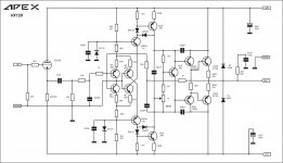
The voltage across the bias transistor was very low, I will show a schematic. There was also no bias going through the emitter transistors.
What happened is eventually Vbe now 0V across the bd139 bias transistor and its got full -45V rail on the output. Before this transistor failed it had 13.8V on the output.
Any ideas what caused the intial condition that blew the bias transistor?
13.8volts on the output means that your vas trannie was not biased correctly...and getting the full -45 volts means that your vas was in full conduction...
i am not sure that your circuit is a good one, was that working good before? doubt it.....
Q7 and Q9 should have been a CCS configured pair....your circuit do not add up...
This sch looks nothing like post1.
Why are you posting in this Thread?
The Darlingtons have a VERY variable hFE. This depends critically on the output current and can vary from a very few thousand to approaching sixty thousand.
At low output current, the very high hFE will result in a tiny base current, so tiny you will not be able to measure it, (there is no base stopper resistor on any of the outputs. There is nowhere to monitor the base current).
You need to monitor the Vbias as well as Vre to see what effect turning the VR has.
Inserting the Vbemultiplier transistor back to front could result in a blow up. The VAS/Sink will apply a high voltage, approaching the rail to rail, if the Vbe multiplier impedes the VAS to Sink current flow. This will fully turn on the Darlingtons and they will probably blow up as well, if the mains fuse does not rupture quickly enough.
This is where using the Mains Bulb Tester for each power ON is so useful.
Andrew, this schematic is from this thread, its called a D14. I bought it from the swapmeet here on DIYA. Both exhibit same behavior.
There is no VR. Vbias is Vre isnt it?
The conditions I mentioned are with no load, its steady state with input shorted. Transistors are not reversed, but of course I dont know its history.
13.8volts on the output means that your vas trannie was not biased correctly...and getting the full -45 volts means that your vas was in full conduction...
i am not sure that your circuit is a good one, was that working good before? doubt it.....
Q7 and Q9 should have been a CCS configured pair....your circuit do not add up...
Nice, I bought a lemon🙂
But it is on this thread, I will find the posts.
one more thing, +-45 is a bit steep, +- 35 volts is more comfortable....
Vc for Q10 is something like([Rcb/Rbe] x 0.6v + 0.6) approximately...
Vc for Q10 is something like([Rcb/Rbe] x 0.6v + 0.6) approximately...
Nice, I bought a lemon🙂
But it is on this thread, I will find the posts.
my thoughts as i look at your scheme more closely...
really, for 2 pairs of output transistors? I thought its about right.
with devices rated for 80volts Vceo, i would think twice putting in +-45 volts...
my experience with those devices is that they easily put out the magic smoke, hence my recommended +-35 volts...
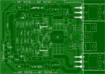
Here is the board overlay for my pcb. He warns about D1, but my D1 is facing the direction of the overlay. I have a capacitance multiplier, I might drop a couple more volts and get it close to 40V.
http://www.diyaudio.com/forums/soli...ltimate-fidelity-amplifier-4.html#post2222198
Its very late here, so i better get some sleep as Im getting careless. I just noticed I lost a rail fuse, maybe that's why I have gone from 13.8 V out to -45. If I get this going I should perhaps replace the outputs with something that can handle the rails as well.
Last edited:
Junction between R12 and R13 should be ground?
Darlingtons are notorious for difficult quiescent current setting. Need to have an adjustable bias, and often higher emitter resistors than usual (1 ohm?). I suspect that the bias was too high, and as the Darlingtons also have poor second breakdown characteristics (derating from 35V) that they may have smoked if the quiescent current was too high.
The MJE340 /MJE350 never have an fT specified. I'd use higher frequency drivers - the stabilisation scheme is generally one I concur with but with slow VAS it might not work.
John.
I bought a couple of boards of a forum member I finally sparked up and they have a fault. This is the DX14 with two pairs of darlingtons. TIP141 and TIP146.
Same in both so it looks like it may be an assembly problem, ie wrong component. I check all resistors and transistors and it looks in order. supply Voltage is +/- 45V.
The voltage across the bias transistor was very low, I will show a schematic. There was also no bias going through the emitter transistors.
What happened is eventually Vbe now 0V across the bd139 bias transistor and its got full -45V rail on the output. Before this transistor failed it had 13.8V on the output.
Any ideas what caused the intial condition that blew the bias transistor?
Have you connected input ground to your main (star) ground point? This design requires the input to be configured like this for correct operation.
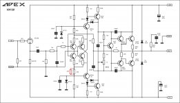
VX120 First Steps
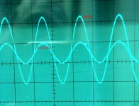
Hi, I started with the VX120 because I wanted to build a hybrid amplifier. The part with the tube I have separated from the amplifier. Comes next. The transistor amplifier running with +- 50V, 40mA bias, sine wave looks good, gain is 30.
Unfortunately, I have -1V offset.
Can anyone give a hint where I start with the adjustment?
Regards Olaf
Attachments
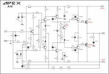
Changes in the schematic (circuit) of the amplifier APEX A10
Hi all!
Can I modify the schematic, if I may that changes to the schematic have to do?😕
Thanks!
Hi all!
Can I modify the schematic, if I may that changes to the schematic have to do?😕
Thanks!
Attachments
Last edited:
Yes.Olaf,
Do you have SGND connected to GND?
Sent from my SM-N9005 using Tapatalk
Ok, I installed a 100k resistor parallel with the 6K8 on the negative side. Offset is now -20mV. Fine-tuning later.
Here is the layout of the tube part. Can be used for 2 channels.
I think that the supply voltage of the amplifier should be very high to provide a suitable anode voltage. Because I currently only have +- 50V (100V for the tube), I'll probably still build a small high-voltage power supply for tests. Was one reason for a separated tube modul.
Every advice and every opinion is really welcome 🙂
Regards Olaf
Attachments

The MJE340 /MJE350 never have an fT specified. I'd use higher frequency drivers - the stabilisation scheme is generally one I concur with but with slow VAS it might not work.
fT of the MJE350 is 10 MHz.
- Home
- Amplifiers
- Solid State
- 100W Ultimate Fidelity Amplifier