Hi Rick,
I see that you say that those two 680R resistors measure alright but are they browned? Just because they still measure doesn't mean they didn't get hot. It might just be that the 47R went first before they got hot enough to fail. I can't find the schematic for the MK2. Double check that you have all the right transistors in the right place and that the layout matches the schematic. I can't think of anything else right now.
I see that you say that those two 680R resistors measure alright but are they browned? Just because they still measure doesn't mean they didn't get hot. It might just be that the 47R went first before they got hot enough to fail. I can't find the schematic for the MK2. Double check that you have all the right transistors in the right place and that the layout matches the schematic. I can't think of anything else right now.
This likely isn't your issue but it looks like you have 22 ohm(22R) emitter resistors instead of .22 ohm(R22).
AHH. Good Point! Will have to get some in. The Combo Pic shows R22. No Schematic i can find, so i will use the Std AX11 one. Thanks
Rick
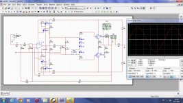
Can anyone help me with this. The 47R resistor outlined in Red Burns up Instantly upon power up. I am using +- 44V rails with 10R/5W resistors in each rail and .5a fuses. I have checked all of the other Transistors & all Test OK.
On this pcb there is wrong polarity on 2N5551... use BC546 or reverted 2N5551 pins (E-B-C to C-B-E)... and use 0,22R/5W instead 22R/5W
Regards
On this pcb there is wrong polarity on 2N5551... use BC546 or reverted 2N5551 pins (E-B-C to C-B-E)... and use 0,22R/5W instead 22R/5W
Regards
AH.. Thank you for correcting this. Will get the new parts & post results in a few days.
Are you using any isolator under the head of the M3 screws.
I do not see that.
greetings
Yes the MJE15030 & MJE 15031 have shoulder washers under the M3 screws. The MJ15003/004 also have insulators. There is No Short from the Heatsink to anything. Thanks for looking .
I'm sure Mile nailed it. Who did this layout and what schematic did they use? I haven't seen either anywhere.
Doing those fixes (0.22R and 2N5551 orientation) plus substituting dead parts will certainly do the job. But it would be also necessary to check inverted transistors life status...
R22 =0.22R The silkscreen in post #5155 is ok.I'm sure Mile nailed it. Who did this layout and what schematic did they use? I haven't seen either anywhere.
Transistors are wrong placed.
Last edited:
R22 =0.22R The silkscreen in post #5155 is ok.
Transistors are wrong placed.
Why do you say that? Pinout for 2N5551 is EBC. It is reversed on the silkscreen in post #5155. BC546 will work fine in those positions.
Apexaudio now that you are back,can you suggest any solutions to make A10 amp work correctly? the problems are reffered at page 510 and back and have to do with output offset.
I'm sure Mile nailed it. Who did this layout and what schematic did they use? I haven't seen either anywhere.
Yes Mile did "nail" it. I replaced all 3 2n5551 & installed correctly.Replaced 22R with R33/5W i had on hand. Powers up but now have +25V on Spk Out. Bias settles at 90mv.
I got this from POST#2201, pg221 by Wiljj78.
Rick
OK I see it. The layout comes from post#2095 which uses BC546. When Wiljj redid it he just changed the name of the part without changing orientation. If you inverted the 2N5551's it should work. I would re-flow all solder joints to make sure you don't have a cold joint.
100W with OP and 2 outputs... just for fun.
You have my attention. Layout? 😀
A reflow & a few other parts and i now have a -1.6V on Spk out & 35.7mv bias across 10r resistor. Thanks for your Assistance.
Rick
Rick
Looks like you are getting closer. Is it -1.6V or -1.6mV? Unless the LTP pair are very imbalanced, you still have a problem. Did you match hfe the input pair?
What is the voltage drop across each of the two R22 emitter resistors? That will help to know the bias.
Thanks, Terry
What is the voltage drop across each of the two R22 emitter resistors? That will help to know the bias.
Thanks, Terry
- Home
- Amplifiers
- Solid State
- 100W Ultimate Fidelity Amplifier