Hello guys
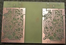
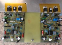
I have an idea because I always have the problem where I can place the power supply board on the case, so I place a capacitor bank and RL on the PCB to see how it looks 🙂
those caps are 22,000uF 63V so far I like the idea what you guys think ?
Regards
Juan
Here is the data PDF and also drop in here Sprint 6 file in the same zip folder
🙂
Regards
Juan
Attachments
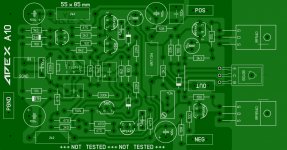
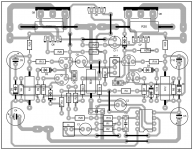
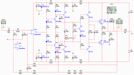
Very first design for the A10. Advice is very welcome.
Next is the detailed examination of the first layout and then we will make a prototype 😀
Regards Olaf
Nice work, pcb is without any mistake as I can see.
Regards
12ax7 sounds really good outputting 5v p-p in the preamp stage.
i am going to use a transistor current buffer to drive the volume pot
i am going to use a transistor current buffer to drive the volume pot
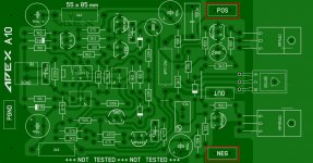
A10 First Layout
Hi,
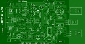
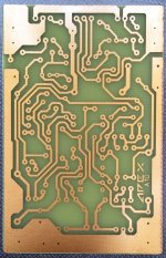
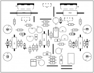
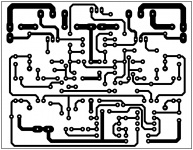
here is the first layout. I have found an error and corrected and etched the first PCB. For those who want to test it (Hi Terry 🙂), here are the Print Files.
Please note: No warranty! Not tested yet!
Hope, I will find the time this weekend to assemble the board.
Regards Olaf
Hi,
here is the first layout. I have found an error and corrected and etched the first PCB. For those who want to test it (Hi Terry 🙂), here are the Print Files.
Please note: No warranty! Not tested yet!
Hope, I will find the time this weekend to assemble the board.
Regards Olaf
Attachments
Hi,
here is the first layout. I have found an error and corrected and etched the first PCB. For those who want to test it (Hi Terry 🙂), here are the Print Files.
Please note: No warranty! Not tested yet!
Hope, I will find the time this weekend to assemble the board.
Regards Olaf
Thanks Olaf,
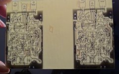
Ready to populate. Wish me luck 😀
Attachments
After if you want there to my version of A9 with TIP142 / 147! 😀Thanks Olaf,
Ready to populate. Wish me luck 😀
Attachments
Hi Terry, looks really good. I started assembling and will report.
regards Olaf
VAS current can be ti high for MPSA... use 2k2 instead 3k3...
Attachments

After if you want there to my version of A9 with TIP142 / 147! 😀
Nice work, is it tested?
Regards
Hello ApexAudio!
The simulation gives very good results.
Thank you!
Not yet because I just finished drawing and I wanted to ask your opinion on a slightly modified scheme.Nice work, is it tested?
Regards
The simulation gives very good results.
Thank you!
Attachments
In trubble
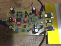
Hi, I started testing.
Voltage is +- 25V DC. Input is shorted and connected to PGND.
Offset is constant around 5V DC.
Quiescent current is adjustable with Poti between 10 and 30 mA measured over the 22R in both rails.
I will change the 3k3 to 2k2. Any suggestions?
regards Olaf
.
Hi, I started testing.
Voltage is +- 25V DC. Input is shorted and connected to PGND.
Offset is constant around 5V DC.
Quiescent current is adjustable with Poti between 10 and 30 mA measured over the 22R in both rails.
I will change the 3k3 to 2k2. Any suggestions?
regards Olaf
.
Attachments
It means trouble - not trubble! Sorry.
With +/-25V 3k3 will bwe ok, but 2k2/2W for zeners must be under 1k... measure voltages on TL071 pins... add 47pF on drivers if you have hf instability...
Hello olafk!
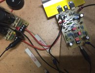
If the colors in the photo are correct, there a reverse polarity compared to your PCB.
Red: POS - Blue: NEG. It's correct?
If the colors in the photo are correct, there a reverse polarity compared to your PCB.
Red: POS - Blue: NEG. It's correct?
Attachments
Last edited:
I have +-13V at TL071, seems not ok. But I will check this.With +/-25V 3k3 will bwe ok, but 2k2/2W for zeners must be under 1k... measure voltages on TL071 pins... add 47pF on drivers if you have hf instability...
Thanks for advice.
regards Olaf
Hi, polarity is ok. I took the cables without looking at the colors 🙂.Hello olafk!
If the colors in the photo are correct, there a reverse polarity compared to your PCB.
Red: POS - Blue: NEG. It's correct?
Thanks Olaf

Looks good. I hope you will not have trouble.
I have also some things to do around the family. So Hobby has to wait.
regards Olaf
I have also some things to do around the family. So Hobby has to wait.
regards Olaf
Same thing on mine. 8V offset. Also, it won't pass a signal. SOmething is not hooked up right. No Time to check now.
- Home
- Amplifiers
- Solid State
- 100W Ultimate Fidelity Amplifier