All good, agreed 👍Unless you guys tell me otherwise, I'm calling both these boards ready for full power.
Dummy place everything into your chassis and put up a pic and we can pitch ideas, from my experience keeping the transformers, and especially the rectifiers, away from the IPS boards gives a way lower noise floor. Transformers will couple a little 50-60hz into the input stage, but the rectifier diodes are the worst for spraying the noise floor with 120hz and harmonics. This noise does not come through the power rail wiring but is instead capacitively coupled by proximity. I like your idea of having the rectifiers above the transformer, so long as they are at the front of the chassis and the IPS boards are at the back. There will be no magnetic field issue with this so long as you don't inadvertently close a mechanical loop through the center of a transformer.
It's up to you how to proceed. You can either do a bench full power test or do the full power test later in chassis with all auxiliary's and speaker protects.
I like to set up (in your case, one of) the intended board power supply on the bench (that's including soft start and ground lift if applicable, but no speaker protect) and test the amplifier at final rail voltage with the heatsink oriented vertically, as it would in the final chassis, to get the bias correct with the right airflow over the heatsink. No need to put in a signal or music if your don't have the means to on the bench. Just gives me reassurance its ready for full rail voltage and is cooling sufficiently as the outputs do generate more heat with final rail voltage as opposed to 30V test rails.
EDIT - always use soft start (or Variac) for transformers larger than 400VA, even when setting up a bench supply. Otherwise you will just end up blowing through multiple Tx input, or output fuses as the caps charge up.

Ok, I'm currently re-reading the wiring document that talks about loop area. I built the chassis when I got it from ModuShop, and then tore it apart to mount the power boards. I'll just mock up one channel for placement. I was told I could use just one SS Board and Ground Lift for both channels, so that's all I've built. Let me know if there's a problem with this.
I used the Quasimodo jig to determine the snubbers for the PSUs. I need to mount to two film caps and the snubber resistors in each of the two psu's.
Then I'll set up a bench test. When you do this, do you utilize the PEM that you're using in the chassis to get mains voltage to the transformers? The PEM I'm using is identical to the one included in the diyaudio store back panel kit (I believe it's unfiltered).
I can provide a signal as my scope has a built in waveform generator. I'm going to build a dummy load with four 16 ohm 100 watt resistors mounted on heat sinks. I also have a preamp and DAC available with old speakers to play through on my bench.
I think I may need to order wire for the power supplies. I was thinking 14 AWG (2.5mm). Service at the wall is better than 120 V 15 A. Come to think of it I think this is the gauge wire Daniel used.....and you guys have 240 V 10 A service. I can't imagine I need heavier than 14 AWG though or can I get away with 16 AWG?
Thanks,
John
The one soft start is fine for both PSU's, but you ideally need 2x ground lifts if doing a full dual mono.
It is probably better to set up the boards for full power in the chassis if you haven't done this before, as you can correctly earth everything that way before applying any mains. You can use the mains entry module from the chassis and make sure all exposed mains terminals are protected correctly, and your PSU and SS boards are lifted off the chassis base with standoffs. A mains setup on bench is risky if you haven't done so before / built a few power amplifiers before.
16awg (1.5mm) is plenty for AC mains, DC rails and amp to speaker terminal wiring, 14awg (2.5mm) is starting to make life difficult for no gain IMO, unless doing something ridiculous like kW amp channels.
@Gianluca is this something that can be added to an order I plan to place very soon?
I would need a CAD drawing with the required holes to drill. After that it should be a breeze to produce one
I can supply you a drawing. Just give me a few daysI would need a CAD drawing with the required holes to drill. After that it should be a breeze to produce one
Its honey badger amp by ostripper with serious community upgrade. I do not see single NP post.
Can you generate drawings for all output transistor types? I am looking for MT200 package drawing if possible.I can supply you a drawing. Just give me a few days
How do you know if a power supply will support being configured for +/-30vdc? Can this one? https://www.volteq.com/linear-power...3005d-3-triple-outputs-30-v-5a-new-model.html
Any two identical “independent” channel power supplies can be configured for dual rail. Bonus if it says they can be run in parallel and series mode. That one is fine.
Last edited:
…Transformers will couple a little 50-60hz into the input stage, but the rectifier diodes are the worst for spraying the noise floor with 120hz and harmonics. This noise does not come through the power rail wiring but is instead capacitively coupled by proximity….
Hi @Mainframe,
Do snubbers help to lower the “spray”? Also, have you found active rectification to be less offensive?
I ask because I’ve noticed this on a different build I am working on and am looking for ways to mitigate it, other than physical distance.
Thanks in advance.
Any pros or cons to using these for the bridge rectifiers vs the design of the Universal Power Supply from DIYaudio?
https://www.mouser.com/ProductDetai...or/GBPC3504-E4-51?qs=AvlKB63p5Skbseqoy9rxVg==
https://www.mouser.com/ProductDetai...or/GBPC3504-E4-51?qs=AvlKB63p5Skbseqoy9rxVg==
The bridge rectifiers you are pointing to are considerably cheaper than using the discrete diodes that require heat sinks on the diyaudio Universal Supply. Not sure about performance differences. Some diodes are fast recovery diodes and are said to reduce/eliminate ringing in transformer secondaries.
You can break off the diode portion of the Universal Power Supply board and use the square bridge rectifier packages, but the discrete diodes sitting on their heat sinks look way cooler😁
You can break off the diode portion of the Universal Power Supply board and use the square bridge rectifier packages, but the discrete diodes sitting on their heat sinks look way cooler😁
I used those on my wolverine build and it sounds wonderful. I also used the Quasimoto to determine the snubber value for my transformer to dampen out any ringing. It was a fun little side project that also gave me piece of mind that I was building the best amplifier I possibly could. I have a couple extra Quasimoto boards from when I ordered them, PM me and I'll send you one. 👍Any pros or cons to using these for the bridge rectifiers vs the design of the Universal Power Supply from DIYaudio?
https://www.mouser.com/ProductDetail/Vishay-General-Semiconductor/GBPC3504-E4-51?qs=AvlKB63p5Skbseqoy9rxVg==
A power transformer snubber is a wonderful thing for reducing or eliminating RFI from rectifier-induced LCR ringing. Unfortunately it's a huge pain to design and optimize a snubber. First you have to measure the transformer's leakage inductance and secondary capacitance, at about 100 kHz, which is not especially easy. Then you have to estimate the capacitance of your rectifier(s), which does not always appear on datasheets. Finally you plug these numbers into a formula that spits out snubber values -- and then you hope it's all correct.
Shown here is a little test jig called...
Shown here is a little test jig called...
- Mark Johnson
- Replies: 2,722
- Forum: Power Supplies
I haven't done any snubber testing yet so can't say. I also haven't done any active rectification testing, although this is something I would like to look into now the new higher voltage capable LM74680 is out in the wild. I suspect active rectification would help a bit in amps with poorer PSRR, but for this case, I just want my Volts back 😊Hi @Mainframe,
Do snubbers help to lower the “spray”? Also, have you found active rectification to be less offensive?
I ask because I’ve noticed this on a different build I am working on and am looking for ways to mitigate it, other than physical distance.
Thanks in advance.
What I can say is: I didn't bother with snubbers, didn't bother with quasimodo's, only transformer out to standard full bridge rectifiers as @RodimusPrime98 linked above, and then onto a cap bank (capacitors only, no resistors or inductors) with a single HF bypass cap circuit (0.1UF+1ohm) on each rail and a rail indicator LED.
This is my wolverine output noise (showing out to 200khz), no mains or rectifier spikes over 1.3 microvolt. (Self-noise of the E1DA ADC shown right to compare)
--
Below shows 5W into 8 ohm, all distortion is from the generator (DAC), not the wolverine, so the spikes to the right of the fundamental can be ignored. Noise floor goes up slightly due to the noise floor of the DAC being amplified.
--
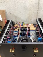
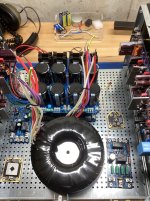
Those captures from this build showing the transformer and cap bank on a platform, with the rectifiers below the transformer. Also under there is soft start and auxiliary power supply for speaker protects.
With results that good, why would I bother chasing snubbers and Quasimodo's. Alongside correct wiring practices, I do wonder how much the high end potted toroidal is contributing to the result. My next build I will use a more traditional un-potted transformer to see if there are any downsides. The platform is made from a single flat piece of steel, raised up on open aluminum frame, so I also suspect there is also some shielding over the rectifiers. The longer power leads no doubt add a bit of L+R between the main cap bank and the local capacitance on the amp boards, too.
For a quick AB with an existing amp with some measurable PSU noise, I would try and get some temporary grounded shielding over the rectifiers, see if it makes any difference.
Last edited:
I wonder if it has anything to do with the 160,000uf filter capacitor bank you've got there?
~132k that one, but I've had the same results with 80k, I suspect the same even for ~40k, due to noise floor alone being a low-load measurement. Ripple gets worse with load yes, that would be another test. The next amp will only have ~40k so we'll see. No doubt its overkill with capacitors, because we can.
Hi Guys,
Big news for the Wolverine 5th Group Buy!
The Wolverine IPS V5, Precision EF3-3 V5, EF3-4 V5, and EF3-5 V5 (Left & Right) boards along with all the Auxiliary boards are now in production! We’ve placed the bulk order, and the boards, complete with their stunning gold ENIG finish, should hopefully ship from the manufacturer in approximately 2 weeks.Once they arrive, I’ll organize packing and shipping to get them to you as quickly as possible.
I’ll reach out to everyone to finalize payment and shipping details via a paypal payment request.
If you haven’t joined yet, there’s still a small window to get in—check out the first post in the Wolverine 5th Group Buy thread for details and email your order sheet to stuartmp@internode.on.net with the subject “Wolverine Project – Your DiyAudio Username.”
A massive thank you to @danieljw, @Mainframe, and the entire Wolverine Team for their incredible work in getting us to this point.
Your patience and support make this project shine! Stay tuned for more updates in the Wolverine Build Thread and Development Thread as we near the finish line.
Best regards,
Stuart (stuartmp)
Wolverine Team
Ok, as big as that 5U chassis from Modushop is, there are only so many ways to orient huge transformers and the Universal Power Supplies from the diyaudio store. I have the two transformers sitting on top of each and would plan some kind plate on standoffs to separate them. The only other thing I can think of is to mount the two transformers vertically on L brackets. That would change the orientation of the EMF generated by them. I have no idea how that would impact performance. Likewise, I am proposing to mount the two Power Supply Boards on top of each other using long M3 standoffs. That would put the rectifiers closest to the front panel and away from the IPS. The rest of it is a SS Board and a Speaker Protector board. The small transformer is needed to power the Speaker Protector circuit, and I would appreciate guidance on where to locate it. At this moment I have only one ground lift board. The other little board is a T ground.The one soft start is fine for both PSU's, but you ideally need 2x ground lifts if doing a full dual mono.
It is probably better to set up the boards for full power in the chassis if you haven't done this before, as you can correctly earth everything that way before applying any mains. You can use the mains entry module from the chassis and make sure all exposed mains terminals are protected correctly, and your PSU and SS boards are lifted off the chassis base with standoffs. A mains setup on bench is risky if you haven't done so before / built a few power amplifiers before.
16awg (1.5mm) is plenty for AC mains, DC rails and amp to speaker terminal wiring, 14awg (2.5mm) is starting to make life difficult for no gain IMO, unless doing something ridiculous like kW amp channels.
Your guidance is much appreciated. I've built an F4 and an F6, but I never tried to cram this much into one chassis. This is my first dual power supply.
John
Attachments
- Home
- Amplifiers
- Solid State
- DIY Class A/B Amp The "Wolverine" build thread