When you get everything together, you need to make the adjustments with the top cover sitting on top. It took me most of a day to get it tweaked.
I'm glad you reminded me. I have to pull the IPS board to recover that resistor as I need to install it in the other channel. I lowered the bias back to zero. I believe the board was pulling something like 485 mA.Perfect and keep an eye on it, it may change in 30 minutes or so. For this test, I think you are done. Lower the bias back down to zero and you are ready for your final power supply. Don't forget to remove the resistor in parallel with R17 before applying your final power supply. Also, how many milliamps was the 1st board pulling, write it down, the 2nd board should be close.
Thanks,
J

Ok, this process is similar to the F4 and F6 amplifiers I built. It's all about the thermal environment inside the chassisWhen you get everything together, you need to make the adjustments with the top cover sitting on top. It took me most of a day to get it tweaked.
J
Hello again,
I am now doing initial testing without output transistors on EF3-4 V 4.0's other channel using a 30V bench supply.
I brought the voltage up slowly and the first thing I noticed is D10 and D11 did not light as they had in testing channel 1. This surprised me, but I carried on.
Output voltage across R111A and R111B measured 758 mV.....exactly as the first channel measured.
I was able to adjust R11 to get 5.0 V so that the proper current is established for the long tail pair.
I measure 593 mV between TP3 and TP4 which just about what the other channel measured.
Voltage between TP-105 and the positive rail and TP-106 and the negative rail were 1.454 and 1.528 V....almost identical to the first channel tested.
My problem is that I cannot zero out the DC offset. It measured a whopping -25.37 V. Adjusting R25 I hit a point where it goes from that negative voltage to a +28.36. No amount of tweaking gets around this issue.
Is this somehow related to D10 and D11 not lighting....or do they not light at 30.0 VDC because here simply isn't enough voltage? What else could I have done to not be able to adjust the DC offset?
I was able to set the output bias to 1.4-1.5V using R109, and it remained stable.
Attachments
Do you have the temporary parallel resistor in place on R17? J103 installed?
Do you have the negative feedback solder bridges installed? Also the TMC jumper
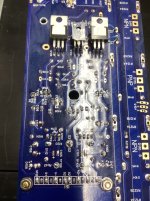
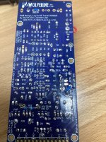
Pic is too blurry to identify any physical errors. But the offset immediately swinging from almost full rail to opposing rail is indication something is not right.
Do you have the negative feedback solder bridges installed? Also the TMC jumper
Pic is too blurry to identify any physical errors. But the offset immediately swinging from almost full rail to opposing rail is indication something is not right.
Last edited:
R17 is installed, and I measured the resistance and it matches what I had on the other channel. The J103 jumper is in. The TMC jumper is in. I have 3 negative feedback bridges soldered on EF3-4 (3rd Group Buy) including Route 2, but not Route 1 (as I assumed they were mutually exclusive).
Could I have reversed those diodes at D10 and D11? Would that cause a problem with DC offset?
John
Could I have reversed those diodes at D10 and D11? Would that cause a problem with DC offset?
John
Attachments
The NFB bridge not being connected I'm almost certain is causing your offset issue.
The LEDs being backward is possibly another issue. Arrows on a diode symbol in a schematic mean the diode is an LED. Arrows on the PCB also indicate the diode is meant to be an LED. In the absolute most basic possible terms, a diode and an LED are the same thing, one just emits light as voltage drops across it, as a nice way to show you that part of the circuit is functioning. (there are many more reasons but lets not get into that here)
Did you get the LEDs to light? If meter in diode mode, the positive on "A" and negative on the other terminal should make the diode light. If it lights the other way, its backwards. If it dont light, she ded.
Last edited:
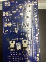
Damn! I missed it. I've got solder on the pads, but they are open!
I am going to have to cut that diode out. It won't drop. I tried adding solder and using the Hakko Desoldering Iron, but it won't give. I have an LED to replace it.
Mainstream, you've got eyes! I'm heading for cataract surgery in the Fall (really).
Thanks,
John
I am going to have to cut that diode out. It won't drop. I tried adding solder and using the Hakko Desoldering Iron, but it won't give. I have an LED to replace it.
Mainstream, you've got eyes! I'm heading for cataract surgery in the Fall (really).
Thanks,
John
Best of luck John with everything, lets get this amplifier running before then eh! 👍
Make absolutely sure you need to take out LEDs first. If you do need to remove the LEDs, they will come out easier if you use a normal soldering iron to bend the legs up vertical first (it appears as though they are bent to help with positioning during install which is okay, but it will make it hard for a desoldering tool to fully remove the solder).
Once it's out you can test it again for function but soldering it back in can be risky as there's only so many heat cycles they can take from the iron (as with all parts). For what it's worth, if you don't have spares, you don't need to source the BOM LEDs if you don't want to wait for mouser. Any 3mm RED LED from a local electronics store will do.
Last edited:
I put it all back together. All 6 LEDs light up. I was able to zero out the DC offset. There's no AC between the output and speaker ground.
Tomorrow I'll install the outputs.
Thanks Mainframe!
John
Tomorrow I'll install the outputs.
Thanks Mainframe!
John
@Gianluca is this something that can be added to an order I plan to place very soon?That can definitely be done, we can extract it from a bigger 3mm thick panel 🙂
I have a problem with the second channel. I'm testing EF3-4 V4.0 with the output transistors installed (with no shorts to ground).. I'm using my bench supply at +/-30 VDC with current limited at 0.3 Amps. J103 has been removed. Input is shorted. 2 Amp fast blow fuses are on the rails. The 9.1k resistor is still in parallel with R17.
I powered up slowly. The LEDs all lit up. I wasn't seeing any bias as I had R109 set at full resistance. I was able to set R11 to 5V. I was also able to adjust R25 to achieve 0 VDC.
Measuring across TP101 and TP102 and adjusting the trimpot I was only able to get to 29.8 mV. Checking back on the DC offset I now had over 5 V. Then I noticed all the LEDs were out except D108 and a very, very dim D107 that slowly faded out. At that point I shut down.
After checking that I had the proper +/-30 VDC coming from the bench supply I tried the board again. No LEDs lit up and I could hear the power supply relays clicking so I shut down again.
Before installing the transistors I noticed when I was insuring that R109 was turned up to maximum resistance that two of the pins on that trim pot appear to be shorted (I think pins 2 and 3). Is that correct?
Confused as usual,
John
This is normalBefore installing the transistors I noticed when I was insuring that R109 was turned up to maximum resistance that two of the pins on that trim pot appear to be shorted (I think pins 2 and 3). Is that correct?
The current limit 0.3A was too low, thats why you were unable to get 44mV bias,I'm using my bench supply at +/-30 VDC with current limited at 0.3 Amps.
The PSU current limit needed to be 0.6A. 29.8mV was hitting the max 300mA the PSU could give, then the power supply began to drop the rail voltage to protect itself as turning the bias up more attempted to pull more current, which is probably why the LEDS faded out.Measuring across TP101 and TP102 and adjusting the trimpot I was only able to get to 29.8 mV.
After checking that I had the proper +/-30 VDC coming from the bench supply I tried the board again. No LEDs lit up and I could hear the power supply relays clicking so I shut down again.
This is probably because R109 was still up (hadn't been reset to max resistance) and the power supply was effectively seeing a short/you were asking too much current of the power supply, limited at 300mA.
My advice - return R109 to maximum resistance between pins 1&2 on the PCB, disconnect the power supply and recheck the resistances as per section 16.3 to make sure nothing is blown, then set the PSU current limit to 0.6A and connect, and try again.
Yes, I forgot to adjust the current and was starving amplifier. I'm going to have to pull the board off the heat sink to set resistance to max. I'm becoming an expert at doing it.
Thanks again,
John
Thanks again,
John
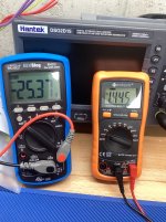
Ok, reset R109 to maximum resistance. Reset bench power supply to 0.6A. Rechecked all resistance readings per 16.3 of the Build Guide and everything checked out. Slowly brought up the voltage to 30 VDC. All LEDs lit up. I was able to get a stable 5 V using R11. I was able to null DC offset; it drifted to 0.08 mV during testing. I was able to tweak R109 to get a stable 41.8 mV. At this point the amp was drawing 0.478 A.
After twenty minutes or so I wound R109 back up to maximum resistance and shut it down.
Unless you guys tell me otherwise, I'm calling both these boards ready for full power.
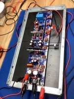
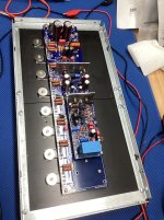
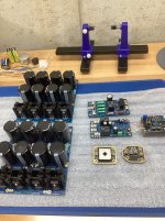
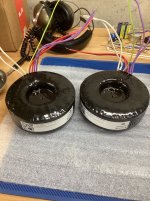
I looked at the wiring diagrams and commentary in that article. I'm not completely sure how to proceed. I have one Toroidy 500 Va transformer and one diyaudio power supply for each board going into a 5U Modushop chassis. I guess I need to start assembling the chassis to see where to place components. Should I wire in the diyaudio SS Module or leave that, ground lift and diyaudio Speaker Protection out of the circuit to start? I'm using fast acting discrete diodes on the PSU pcbs. What do you think of mounting the PSUs on 80mm standoffs right above each transformer? Or does that put the rectifiers too close to the magnetic fields created by the transformers? Secondaries are dual 50V (red red and violet violet). Is the green and yellow wire labeled "0" the PSU ground rather than a shield? It must be because there aren't any other wires other than the primary (white white).
Let me know what you think.
And I cannot tell you in words how grateful I am to everyone who has helped me get this far. This is everything anyone could ever hope for from a build forum.
Many thanks,
John
After twenty minutes or so I wound R109 back up to maximum resistance and shut it down.
Unless you guys tell me otherwise, I'm calling both these boards ready for full power.
I looked at the wiring diagrams and commentary in that article. I'm not completely sure how to proceed. I have one Toroidy 500 Va transformer and one diyaudio power supply for each board going into a 5U Modushop chassis. I guess I need to start assembling the chassis to see where to place components. Should I wire in the diyaudio SS Module or leave that, ground lift and diyaudio Speaker Protection out of the circuit to start? I'm using fast acting discrete diodes on the PSU pcbs. What do you think of mounting the PSUs on 80mm standoffs right above each transformer? Or does that put the rectifiers too close to the magnetic fields created by the transformers? Secondaries are dual 50V (red red and violet violet). Is the green and yellow wire labeled "0" the PSU ground rather than a shield? It must be because there aren't any other wires other than the primary (white white).
Let me know what you think.
And I cannot tell you in words how grateful I am to everyone who has helped me get this far. This is everything anyone could ever hope for from a build forum.
Many thanks,
John
Attachments
- Home
- Amplifiers
- Solid State
- DIY Class A/B Amp The "Wolverine" build thread