Hi guys,
I'm preparing to install the output transistors on EF3-4 V. 4.0 boards. I know trimpot R109 gets set back to maximum resistance. What about R11 and R25? Put them back to their mid-points for powering up with the output transistors installed for the first time?
Thanks,
John
I'm preparing to install the output transistors on EF3-4 V. 4.0 boards. I know trimpot R109 gets set back to maximum resistance. What about R11 and R25? Put them back to their mid-points for powering up with the output transistors installed for the first time?
Thanks,
John
Hi John,
I would suggest to leave the DC offset (R25) the same and CCS1 (R11) the same if you are using your lab supply.
After everything is checked and working then reduce CCS1 (R11) only in preparation for the amplifier power supply voltage.
When you change to your intended full supply voltage make sure you reduce Bias and CCS1 again first.
- Dan
Last edited:

Yes if you are using your lab supply and can bring the Voltage up slowly
John I am hoping this step goes smoothly for you and you are soon to be listening to a very high performance amplifier.
- Dan
- Dan
Thanks Dan. I hope so too because I have to repeat all this with the other channel (which is already built). And then I have to wire in the power supplies, ground lift, soft start and speaker protection. All the boards for the auxiliary stuff are built, but it's a lot of stuff to get right.....
John
John
Just break it down into small steps and take your time it will all work out in the end
Looking for recommendations on where to purchase the lab equipment (mainly the power supplies) needed to complete this build.
Why not use the transformer and rectifiers / filters you are going to use. Use a variac to slowly increase the AC mains voltage so you have a slow start-up? The only extra piece you would need is the variac (with current meter). Variacs are very useful when working on electronics powered from the mains.
That is how I do it too, but I will note we do advise against it in the build guide. Only because if you are a novice builder with only 1 or 2 builds under your belt, we'd hate to see someone make a costly mistake damaging their nice big caps or transformer.
If you are confident enough, with a separate old junk transformer (doesn't need to be big for testing at all, approx. 100VA+ would do it) with suitable secondary voltages and a couple decent size caps lying around, buy a Variac and make an analogue bench supply. Mine doesnt have a current readout only voltage so I use 1000mA analogue ammeters in line with the amplifier rails to get a nice read on what's happening as the voltage comes up. Also use a fast 1A fuse at the transformer primary input (often on the Variac output) and ~2A fast fuses in line with the transformer's secondaries.
Of course, the ongoing use of purchasing boxed bench PSU's with current limiting is the real attraction.
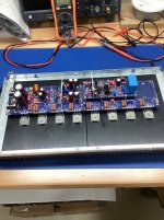
Ok guys, it's past 2:00 am here in Pennsylvania, but I wanted to get this one channel prepped for testing with the output transistors installed. So I removed the J103 jumper, the output transistors are installed with non-magnetic stainless spreader washers and M3 split washers. I elected to use sil pads. I checked each transistor leg for a short to the heat sink. No beeps. R109 is set to maximum resistance. The input is shorted. I passed all the resistance tests too.
Please take a look and let me know if you see anything suspicious. Testing will commence with my bench power supply later today (Saturday).
Thanks,
John
Please take a look and let me know if you see anything suspicious. Testing will commence with my bench power supply later today (Saturday).
Thanks,
John
Attachments
Since the drivers and bias transistor are also bolted to the heatsink; did you test those for continuity to the heatsink? You can also test the transistors bolted to the separate aluminum upright heatsinks. If all those test good, put the power to it.
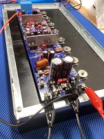
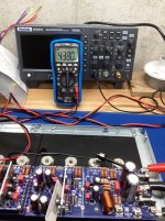
I have the one Wolverine channel powered at 30 VDC with the output transistors installed. R11 was almost spot on at 5 V. I have no DC on the output and AC voltage measures zero. I have the bias set to 00.4 mV using R109. I thought the bias would bounce around, but once it settled it just stays there
One thing bothers me. I'm measuring the bias with a very inexpensive Neoteck meter. When I try to measure the bias on my Brymen BM235, I get a zero DC reading. Manually changing the range does not change anything. Yet I can read the 5 VDC between TP1 and TP2 with the Brymen......just wondering....
One thing bothers me. I'm measuring the bias with a very inexpensive Neoteck meter. When I try to measure the bias on my Brymen BM235, I get a zero DC reading. Manually changing the range does not change anything. Yet I can read the 5 VDC between TP1 and TP2 with the Brymen......just wondering....
Attachments
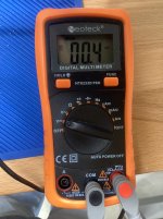
Bias should be 44.0mV, not 00.4mV. You got a few more turns of R109 to go 😉 pay attention to the scale the meter is showing. (Does it show mV or just V, etc.)
The other meter you have is probably not capable of auto ranging and is only set to measure "V" therefore 00.4mV will show is 0.00V, and it is not set to the correct mV range, or in some cases it may not be capable of even measuring mV (unlikely, unless its a linesmans meter). Either way, it won't show 4 tenths of a millivolt like your pictured meter is, until its range is corrected or you get a meter with more measurement range like the Neoteck.
EDIT - just looked up that Bryman - it needs to be set to mV range and then select manually into DC to measure mV DC.

Meters have ranges they measure in and these either need to be set manually or auto range. It is up to the user to pay attention to what range is being displayed on the screen if the meter autoranges. The neoteck meter you picture appears to be of autoranging type, and it will display mV or V accordingly.
The other meter you have is probably not capable of auto ranging and is only set to measure "V" therefore 00.4mV will show is 0.00V, and it is not set to the correct mV range, or in some cases it may not be capable of even measuring mV (unlikely, unless its a linesmans meter). Either way, it won't show 4 tenths of a millivolt like your pictured meter is, until its range is corrected or you get a meter with more measurement range like the Neoteck.
EDIT - just looked up that Bryman - it needs to be set to mV range and then select manually into DC to measure mV DC.
Meters have ranges they measure in and these either need to be set manually or auto range. It is up to the user to pay attention to what range is being displayed on the screen if the meter autoranges. The neoteck meter you picture appears to be of autoranging type, and it will display mV or V accordingly.
Last edited:
There are several turns but then it will take off. Keep an eye on it, you may need to adjust it back down as it starts to get some heat into the main heatsink.
Later on, when you have the final rail fuses in as per sheet 2 for burn in (you're not quite there yet), this is best done with the heatsink vertical if you can, to get airflow across the fins. It makes a big difference.
Later on, when you have the final rail fuses in as per sheet 2 for burn in (you're not quite there yet), this is best done with the heatsink vertical if you can, to get airflow across the fins. It makes a big difference.
Ok, I still have R109s resistance set too high as the voltage is low by a factor of 100.
I just looked at the picture you sent of my Brymen meter. Apparently I don't know how to use my own tools!
You are saving me from jumping out the widow....,,
Thanks!
I just looked at the picture you sent of my Brymen meter. Apparently I don't know how to use my own tools!
You are saving me from jumping out the widow....,,
Thanks!
Perfect and keep an eye on it, it may change in 30 minutes or so. For this test, I think you are done. Lower the bias back down to zero and you are ready for your final power supply. Don't forget to remove the resistor in parallel with R17 before applying your final power supply. Also, how many milliamps was the 1st board pulling, write it down, the 2nd board should be close.
- Home
- Amplifiers
- Solid State
- DIY Class A/B Amp The "Wolverine" build thread