''''without coloration'''' Do you feel happy with that ?Control, range without coloration, speed, the first impressions.
its an ""excellent amplifier, rock steady ,powerfull "" but when i change this amp in the same system with another Class A amp ( AN39 ,Hiraga le Monstre , USSA 5) i feel uncomfortable....
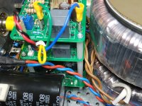
Last change i put two soft Start each one for each trafo 500VA, plus a DC Blocker.
Attachments
Last edited:
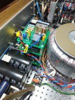
I see a tiny part of an Analysis planar speaker on the second picture. I have never heard those, but have Apogee Duetta's myself. Your amplifier looks great!The final touches were done.
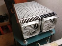
And I took it up to my living room,
Control, range without coloration, speed, the first impressions.
For me, it is the best amplifier I have ever built.

Nikos, What makes it uncomfortable? Power surge? Or Could you elaborate?but when i change this amp in the same system with another Class A amp ( AN39 ,Hiraga le Monstre , USSA 5) i feel uncomfortable....
Do you find that the amplifier lacks some of the magic of your class A amplifiers? And that, at the same time, the Wolverine has qualities that the other amplifiers don't have?''''without coloration'''' Do you feel happy with that ?
its an ""excellent amplifier, rock steady ,powerfull "" but when i change this amp in the same system with another Class A amp ( AN39 ,Hiraga le Monstre , USSA 5) i feel uncomfortable....
Last change i put two soft Start each one for each trafo 500VA, plus a DC Blocker.
Greek company, has many similarities with Apogee.I see a tiny part of an Analysis planar speaker on the second picture. I have never heard those, but have Apogee Duetta's myself. Your amplifier looks great!
I have added 2 18 inches speakers
For the low frequencies, which are driven by the ROTEL RB-1590 and for the analysis
The Wolverine crossover is used
Xta db224,
In a future upgrade I will add another amplifier for the ribbon with a
3-way crossover.
I get two toroidal trasformers Talema 2x0-40v AC at 1000VA.
They have a mechanical noise due to wiring vibrations.
If I fill the center hole with an epoxy resin , can I lower that noise?
Thanks
They have a mechanical noise due to wiring vibrations.
If I fill the center hole with an epoxy resin , can I lower that noise?
Thanks
Yes, I had to do the same thing with my Honey badger build.They have a mechanical noise due to wiring vibrations.
If I fill the center hole with an epoxy resin , can I lower that noise?
Thanks
Please see the last few photos in my build album for details
I also have four 600VA transformers that I don't use now because they are not quiet enough. I see in one of the pictures you used a product named KX-flex 60. This is a flexible resin and is different from the hard resin usably used by transformer manufacturers. Has it been completely effective and was there a reason for choosing 60A shore hardness?
Peter
Peter
Yes....Do you find that the amplifier lacks some of the magic of your class A amplifiers?
For a big wattage ampifier its an excellent amplifier, rock steady ,powerfullAnd that, at the same time, the Wolverine has qualities that the other amplifiers don't have?
Attachments
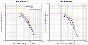
I tested the overcurrent protection circuit that I posted previously (post #5430 with R27 and R28 set to 470 ohms) on a test bench with substitute Re resistors (two 0,47ohms resistors in parallel). So I did not test this circuit in the actual amplifier yet. This is a single slope protection circuit. At Vout=0V the circuit trips at 5A, while at +/-42V maximum swing output (for a +/-55V power supply) I get 0.9A and 9.1A. I plotted my results on the SOA of output transistors NJW3281G and NJW1302G and as you can see the tripping limit is within the 100ms SOA. Can any of the experts out there tell me if this will provide an adequate protection of the output transistors?
Attachments
Driver VAS Stage test
TTA004B---- 84.8 ( 10ma - ic) 184 v HV test
2SA1381-----11.2 ( 10ma - ic) 448v HV test
KTA1381-----15.9 ( 10ma - ic) 389V HV test


TTA004B---- 84.8 ( 10ma - ic) 184 v HV test
2SA1381-----11.2 ( 10ma - ic) 448v HV test
KTA1381-----15.9 ( 10ma - ic) 389V HV test
Hi all, I try to beta match the KSC3503 with the KSA1381and it look quite challenging. have some of you choose\replace those semi with other type without any issue on matching? Thank you Mario
Don't forget the long term instability of optocouplers! That is the reason not to use them in analog circuits. (at least not without appropriate countermeasures) My circuit does not change trip level over time because of constant current on the optocoupler LED.I tested the overcurrent protection circuit that I posted previously (post #5430 with R27 and R28 set to 470 ohms) on a test bench with substitute Re resistors (two 0,47ohms resistors in parallel). So I did not test this circuit in the actual amplifier yet. This is a single slope protection circuit. At Vout=0V the circuit trips at 5A, while at +/-42V maximum swing output (for a +/-55V power supply) I get 0.9A and 9.1A. I plotted my results on the SOA of output transistors NJW3281G and NJW1302G and as you can see the tripping limit is within the 100ms SOA. Can any of the experts out there tell me if this will provide an adequate protection of the output transistors?
found the issue. ThanksHi all, I try to beta match the KSC3503 with the KSA1381and it look quite challenging. have some of you choose\replace those semi with other type without any issue on matching? Thank you Mario
Hi Guy's,
I have attached a preliminary 64v rail schematic for the Wolverine V5.0 to the first post.
The schematic is complete however we may just add some extra notation as we work through the final release builds and reviews from the Wolverine Team.
A big thanks goes out to @Harry3 for developing the BOM and @Mainframe for his though checking, suggestions and creating the mouser carts.
H guys, I'm new to the wolverine thread. Purchased boards and parts last November and have been (very slowly) populating the boards. They are almost ready to test. Doing 71v rails with 2SC2922 / 2SA1216, and probably will be using the Cobra SMPS. Can't wait to finish the build.


Hi Guy's,
Exciting news! The Wolverine V5 boards have landed with @Mainframe! These boards are our test builds to ensure everything is 100% spot-on and verified before we place the bulk order for the 5th Group Buy. The final group buy boards will feature a premium gold ENIG finish, giving them a stunning look and enhanced durability.
A huge thank you to @Mainframe for capturing these images so promptly—check out the photos in the 1st post to see the V5 boards! Stay tuned for updates on the verification process in the Wolverine Build Thread as we confirm these boards are ready to rock.
A big thanks to the Wolverine Team and to all of you for keeping this project thriving!
Best regards,
Stuart (stuartmp)
Wolverine Team
Hi all Wolverine builders!
I am finally found time to go on with my Wolverine-EF3 project. For this purpose I have read carefully the documentation received with the PCBs. Some details in the documents were not fully clear for me and raised The following questions:
1 On sheet 2 of the BOM, selection criteria of the power transformer and proposal for the power supply can be found. In case you have a normal toroid transformer with two separate secondaries, a circuit with a separate rectifying bridge for each winding is recommended. I made a reasonably thorough simulation comparison of that circuit and another circuit, where the transformer secondaries are connected to one rectifier bridge like in the other circuit example using a transformer having one secondary winding with fixed center tap. For the simulation I checked the properties of a real 300 VA, 220/30/30 V transformer by measurements and used in the simulation such transformer model, which behaved like the measured transformer. In this comparison I did not notice any differences, which would affect the performance of the amplifier. The only differences were additional voltage and power loss caused by additional diodes. Now I am asking: why a circuit with two separate rectifier bridges is recommended for the power supply?
2 I am considering two alternatives for the power supply of a stereo amplifier, one with a 600 VA transformer common for both channels and another with separate 300 VA transformers for each channel, in fact a double mono construction. I got this idea when I found that two power supplies coud be housed in a 4U enclosure. This causes naturally additional costs and now I am wondering if it woud result in any better performance. I would welcome your opinions.
3 I am also thinking how to dimension and select the power supply filter capacitors. Just now I cannot find any recommendations in the documentation, but I have the feeling that somewhere minimum 2 x 10 000 uF for both positive and negative rails has been recommended for the power supply of a stereo construction. If a double mono construction is selected, would a smaller capacity like 10 000 uF for each rail be enough? Any recommendations for good capacitor types with reasonable prices for 54 V rail voltage?
4 On sheet 2 of the BOM a table containing information about alternatives for capacitors C115 nad C117 can be found. For each alternative ripple figures for 100 Hz (in fact the column heading is 100 kHz) and 120 Hz as well as impedances are given. For me it remains unclear how to use this table for the selection of C115 nad C117. Could somebody explain?
5 In item 12 of the Build Guide, the instrucion asks to wind the output coil L1 clockwise. The instruction with a picture is clear, but I am curious to know why clockwise. Woud the magnetic field of the coil cause a harmful feedback, if wound counterclocwise?
I remain waiting with interest for the response of anybody, who knows.
Martant
1. Discussed here https://www.diyaudio.com/community/...he-wolverine-build-thread.385920/post-7664715. I too have built and measured with both center tapped and dual secondary arrangements and found a slight noise floor improvement using the dual secondary set up with dual rectifiers. However the improvement was something like 2-3uV so could have been measurement error. It's not necessary to go dual secondary, but if you buy dual secondary transformer, you can set it up for either dual or single rectifier anyway. 👍
2. There is arguable improvement by going dual mono as the ground is not shared across channels, better channel separation and SNR. https://www.diyaudio.com/community/...he-wolverine-build-thread.385920/post-7565212
3. 10,000 uf (with 300VA traffos) would be fine so total 20,000uf per channel, total 40,000uf for stereo.
4. Higher ripple means the capacitor is more robust - it can handle the heat of a higher sawtooth DC wave. This increases as the demand on the transformer is increased (so playing at higher volumes). All the caps on sheet 3 are suitable but if you plan on doing full power testing into resistor banks you may want to favor higher ripple. Lower impedance is also better, means the capacitor acts less like a resistor to the power passing through it. The best value part here (for lower than 63V rails) is EKYB800ELL102MLP1S. Its cheap and robust.
5. Direction of the wind doesn't matter; it just matches the board footprint if you go clockwise and fits much nicer.
Check out https://www.sound-au.com/ articles / power supply design for a very objective deep dive on power supplies if you want more info.
- Home
- Amplifiers
- Solid State
- DIY Class A/B Amp The "Wolverine" build thread