It probably wouldn't make a sonic difference, but it could. For one, THAT is a very very small company with their own Fab and monolithic process and they exclusively do audio, so theres that.Would THAT make any sonic difference?
What THAT does talk about on the datasheet are optimizations for device protection when the balanced output is presented a dysfunctional load. So, it may give you more stability/resiliency when plugging in the Pearl 3 to unknown downstream gear. There is also another optimization so that the balanced out semi-behaves when connected to a single ended input (again, a type of dysfunction in downstream gear with "XLR" inputs).
I do know that THAT shows up in alot of bespoke studio and recording gear. So, theres that. (PUN! 🙂 ) My original question - should Ferrite Beads be in the Balanced Output circuit as this datasheet recommends? (Possible change request for new board revisions)
Installing ferrite beads...why bother with THAT, you asked..
Well, following datasheet recommendation never hurt nobody...however, from browsing the specs, they also say it's not necessary.
Incorporating diodes and ferrite beads seems like an overkill to me.
Well, following datasheet recommendation never hurt nobody...however, from browsing the specs, they also say it's not necessary.
Incorporating diodes and ferrite beads seems like an overkill to me.
Merry Christmas and Happy Hannukah to all. Thanks for the help with another awesome DIY project!! Huge best wishes to Jim, Wayne and the omnipresent Zen Mod. You guys have provided such incredible content and great support, and amazingly you’ve kept me from electrocuting myself.
So far.
So far.


OK, enough pussy footing... this is Christmas, not some Shinto Rock Spirit Holiday.
Bon Nadal
Got my Nadal Gifts... always give more than you take... that way you won't feel one bit guilty about those boxes coming in at the front door that mysteriously get sidetrack to the home office at the front of the house before anyone else sees them. ;-)
It was a Great Year. So far... Wait 'till I power up the Sony/DIY VFET amp.
BTW, GREAT PHONO P3 NEWS.. not only does the balanced output of the P3 sound really good.... but I told my wife that next year I won't by getting more amps (*), but I will need 5000 bucks to get a the Keel and Ekos tonearm. She didn't flinch. Didn't tell me no, didn't call me nuts. I guess it's OK so long as I keep working.
(*) Well, there's that darn SIT5. And I still hold some hope for returning to a "high power" 252SIT like someday. I wonder is she'll notice if I add one more shelf to the amp racks?
Last edited:

I figured, maybe I can get modushop to one off a similarly cut front panel. Already....feeling force to.....build....another one?@Russellc: Am using Randy's FlexReg PSUs and they are too tall for the custom chassis. Use any of Gianluca's 2U models -- they are inexpensive.
@tonyEE: You can buy any length of cable from raw cable, just change the value here.
https://www.rawcable.com/cable/1800F.htm
And for those of you keeping track of prices, in 2020, 200 feet of Belden 1800-f was $169.62. Four years later it is $340 -- almost twice as much.
Russellc
The happier they are, the less they see. Seems simple, it cost me two marriages and a couple piles of money to learn that.....along with "two can live as cheaply as one" is a crock of it. I keep seeing Cartman's face "I do what I want" rant...sort of.OK, enough pussy footing... this is Christmas, not some Shinto Rock Spirit Holiday.
Bon Nadal
Got my Nadal Gifts... always give more than you take... that way you won't feel one bit guilty about those boxes coming in at the front door that mysteriously get sidetrack to the home office at the front of the house before anyone else sees them. ;-)
It was a Great Year. So far... Wait 'till I power up the Sony/DIY VFET amp.
BTW, GREAT PHONO P3 NEWS.. not only does the balanced output of the P3 sound really good.... but I told my wife that next year I won't by getting more amps (*), but I will need 5000 bucks to get a the Keel and Ekos tonearm. She didn't flinch. Didn't tell me no, didn't call me nuts. I guess it's OK so long as I keep working.
(*) Well, there's that darn SIT5. And I still hold some hope for returning to a "high power" 252SIT like someday. I wonder is she'll notice if I add one more shelf to the amp racks?
Russellc
There already is Mark's "rolling" op amps in P3 thread.....rolling ...hmmmJim being poetic... please do so.
I've been so good having projects NOT look like they belong in Her Frankenstein 's laboratory with these custom boxes...OK, enough pussy footing... this is Christmas, not some Shinto Rock Spirit Holiday.
Bon Nadal
Got my Nadal Gifts... always give more than you take... that way you won't feel one bit guilty about those boxes coming in at the front door that mysteriously get sidetrack to the home office at the front of the house before anyone else sees them. ;-)
It was a Great Year. So far... Wait 'till I power up the Sony/DIY VFET amp.
BTW, GREAT PHONO P3 NEWS.. not only does the balanced output of the P3 sound really good.... but I told my wife that next year I won't by getting more amps (*), but I will need 5000 bucks to get a the Keel and Ekos tonearm. She didn't flinch. Didn't tell me no, didn't call me nuts. I guess it's OK so long as I keep working.
(*) Well, there's that darn SIT5. And I still hold some hope for returning to a "high power" 252SIT like someday. I wonder is she'll notice if I add one more shelf to the amp racks?
Especially around the tiny bits....@stereonutty
there have been several reports over the course of this project where difficulties have been resolved by careful cleaning of PCBs especially of flux around solder pads and leads.
just sayin'
@Craigl59
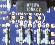
I found the cause of my problem. It was with the SMD fets after all, but not that any were not soldered "enough", but more that one was soldered "too much". The SMD source pad is very very close to the gate through hole, and I thought I checked all SMDs to see if I did not accidently connected those. But apparently I missed one(!) See picture. Btw the very first one a put on. Thank you very much for your help CraigI59, without you I never would have found it!
Cleaned the solder up and now I have sound from both channels and most of the noise is gone. But alas, I also have a new problem now: a clearly audible and persistent hum (when my recordplayer is connected).
Attachments
Have had similar over-soldering issues and know just what you went through. Glad you are up and running.
SMDs are no end of difficulty and I have developed a new one with my BA2018 premium build boards (that match all of the transistors including the SMDs). The second of these built boards works fine for the first 20 minutes or so then the left channel drops down 6dB. Continues this way for the rest of the listening session. Am also going to try and clean up the SMDs on this board and hope that improves the issue. But it seems more likely that one of the SMDs is failing after a certain temperature is reached.
Hum typically takes you to the ground arena where I do not like to visit. Do you think the hum is P3 related or caused by your TT?
Not sure. I ran my TT previously through the build in phono stage of my old integrated, and lately I did hear the same kind of hum that way too. Just not that loud. The cable I use for that is (a bit improvised) DIY, and I did a lot of pluging in and out because of my P3 problem.Do you think the hum is P3 related or caused by your TT?
J112 Matching and other stuff
Have been intrigued by the current differences over R27 that occurred on all 3 of my P3 builds.
So, taking the info provided by 6L6 and grataku, ordered a bunch of different kinds of J112s and have been measuring them and trying some of them out.
Here are results.
FIRST, here is the starting build that was adjusted to get even current: Left R27= 2.969V with a 650 ohm resister = 4.567mv. Right R27=2.782V with a 600 Ohm resistor = 4.6367mV. Fairly close current after R adjustment and the unit sounds perfectly fine (like a regular P3).
THEN...
Got some premium low-noise JFets from Mouser, (#106-112) and matched two of them carefully. See MatchedJ112s (low noise) below. These more expensive J112s ($3.25 a piece) come closely matched. Tracings are close and, each J112 trace ends at almost exactly the same spot (have been told this is most important for matching). Then installed the same, 650 ohm resistor value on each board.
AND THE BIG REVEAL...
Left channel reads 3.062 V with the 650R = 4.71mV. And the right channel reads 3.009 V with the same 650R = 4.629mV. This is much closer that the old, stock J112s and here's why. The original, stock J112s were run through the Atlas D75 analyzer and you will see the results at OldJ112sUnhmatched below. Note the great variation in the trace height AND especially note how the two J112s disagree in their ending points. No wonder, then, that the current is so different among boards with the stock J112s.
But how do they sound?
Oh Boy! This is where the big interest lies!
Put the revised P3 into the Winter System and noticed, first of all...
...Oh-oh. Is that a knock at the door? Hold on, guys, I'll be right back.
Hope it's not that tea sales guy again. We all hate it when the Teamann arrives, right?
Attachments
this transistor-resistor combo is a constant source, right?
back when dinosaurs ruled the earth Richard Marsh drew a single device for this purpose in his Pooge-3 line stage: the 1N5314.
no fuss no muss. but expensive.
back when dinosaurs ruled the earth Richard Marsh drew a single device for this purpose in his Pooge-3 line stage: the 1N5314.
no fuss no muss. but expensive.
Linear Systems has recreated the entire Siliconix product line of two terminal current source devices. Here they are.
Today the worldwide semiconductor industry has chosen to name these kinds of products "Current Regulating Diodes". Mouser.com sells over a thousand different CRDs, this is a link to their sales page.
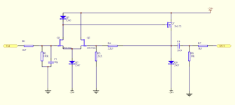
I have attached a schematic which purports to be the line stage of the Threshold FET2 preamp, designed by Nelson Pass in the early 1980s. You can see it uses three of the Siliconix current regulating diodes.
Today the worldwide semiconductor industry has chosen to name these kinds of products "Current Regulating Diodes". Mouser.com sells over a thousand different CRDs, this is a link to their sales page.
I have attached a schematic which purports to be the line stage of the Threshold FET2 preamp, designed by Nelson Pass in the early 1980s. You can see it uses three of the Siliconix current regulating diodes.
Attachments
Hello,
The OPA1656 is my pick of the litter.
In terms of measured distortion they all challenge even the best analyzer.
Thanks DT
A bit late to the party… for what it’s worth, the 1656 was our favorite too when a friend and I did comparative listening in the Pearl 3. He left with the Pearl 3…
- Home
- Amplifiers
- Pass Labs
- Pearl 3 Burning Amp 2023