I powered up my amp with the 2 amp PCBs disconnected from the PSU board as a first test and it seems to have gone smoothly. The bulb light up slightly for under 1 second. Now I want to connect 1 amp board at a time to continue testing. I want to drain all 12 capacitors on the PSU.
What is the sure way to drain all caps? Since it's so critical, I'm asking first. I'm guessing touching a 100ohm resistor between GND->Rect A+, GND->Rect A-, GND->RectB+ and GND->RectB- will do the trick?
What is the sure way to drain all caps? Since it's so critical, I'm asking first. I'm guessing touching a 100ohm resistor between GND->Rect A+, GND->Rect A-, GND->RectB+ and GND->RectB- will do the trick?
100 ohms might get a little warm. I'd suggest using two 100 ohm resistors in series, that way each one only gets half as hot. Alligator clips / crocodile clips are a convenient way to grab the resistor assembly, then touch the other ends of the clips to the cap. Hold there for about three seconds. Then if you're super paranoid, put a screwdriver shaft across the cap terminals to drain away the last few nanoCoulombs of electric charge. I.e. to reassure your fevered paranoia that "it might not be COMPLETELY empty"
you can use your bulb tester to drain caps
pull plug from the wall outlet, connect pair of crocs to plug, then short caps with crocks
pull plug from the wall outlet, connect pair of crocs to plug, then short caps with crocks

I keep a 2k 3w resistor floating around. I generally go form V+ to V- with it and let it sit for a few minutes. I used it the other day and it took about 2-3 minutes to drain 240,000uF of el caps at 48vdc across V+ to V-.What is the sure way to drain all caps? Since it's so critical, I'm asking first. I'm guessing touching a 100ohm resistor between GND->Rect A+, GND->Rect A-, GND->RectB+ and GND->RectB- will do the trick?
I connected two 120ohm resistors in series to a CROCK ( aka aligator clip ) and drained them that way. I'll hold them longer next time since I only touched them for a second or so. I checked voltage though it it was under 1V.
I also turned the amp on with both amp boards connected and the bulb lit up slightly for under 1 second and then went out. Should be all set for tuning but I'll let it run for 30 minutes or so to see if anything blows up or smells.
I also turned the amp on with both amp boards connected and the bulb lit up slightly for under 1 second and then went out. Should be all set for tuning but I'll let it run for 30 minutes or so to see if anything blows up or smells.
If the bias is stable and the DC offset is reasonable, then let her rip! 🙂 I would have already been running towards my most favorite pair of speakers with it by now. But I am very impatient... 😬
Don’t set your bias with the dim bulb tester connected. You may start your bias procedure just to see if you get it going, but I would not go further than say .2v before shutting down and removing the dbt.
Ok, I'll need to learn more about tuning before going nuts and connecting it to my brand new wharefdale super lintons. ( blow them up ).
I posted my personal 'build cookbook' for my F5m if anyone want to use it as a reference. It's not a guide by any means but new builders can see pictures of my build if that helps any. ( some content was not posted here, and some of it was based on answers received here )
I posted my personal 'build cookbook' for my F5m if anyone want to use it as a reference. It's not a guide by any means but new builders can see pictures of my build if that helps any. ( some content was not posted here, and some of it was based on answers received here )
I intend to use this thread to document my F5m build and serve as a build guide for others.
UPDATE Nov 30 2024:
I have finished my F5m build and it powered up without issue so I'm ready to post a document for anyone who may find it useful.
It's actually not a Guide, but more of a cookbook for my own build. I will leave the official guide to experts who are much more knowledgeable than I am.
The document contains notes I initially made for myself so there could be typos and other errors. I made it available rough instead of waiting for a fully edited copy since it could help new...
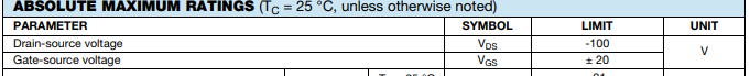
I'm sure I'm reading something incorrectly; The datasheet for IRFP9140 shows the max rating for the gate at +-20V. If R8 is set to 0, will Q3 get +24V at the gate? ( R8 set to 100% ) I guess the 1K resistance will ensure it won't reach 20V on the gate? I'm sure it's something I'm overlooking but thought I would ask. UPDATE: I figured this one out. I see it's a P mosfet 🙂 The gate would see 52mV if R8 is 100% is I'm getting it right.
I attached a screenshot of the Gate-Source max voltage.
Still curious:
What voltage should I see across R6 when both R8 and R9 trims are at 0?
What voltage should I see across R6 when both R8 and R9 trims are at 100%?
Can damage be caused to the amp board if the R8 and R9 trims are at 100%? ( with no speakers connected )
Attachments
Last edited:
I would suggest carefully reading the nice tutorial in the F5 product manual for a better understanding of the complementary Common-Source stage and it's relationship to the gate to source voltage necessary to get the power MOSFETs into conduction. You'll want R8 and R9 fully counterclockwise to start and carefully sneak up on the setting (G-S voltage) that allows the desired current to flow through the output stage. If you plan on cranking the pots full clockwise, let me know first so I can leave the room..
@william2001 thanks for mentioning the F5 product manual, it's going to answer many of my questions. I see the specs are a bit different but that is expected. I wanted to understand the circuit a bit better before tuning.
When you ask to leave the room, is it because the P-Channel IRFP9140's gate can reach as low as 51mv if trim R8 is turned to full, surpassing the Vgs +-20V max threshold ( datasheet ) and blowing out, sending pieces in your general direction? If so, let me know so i know I understand correctly.
When you ask to leave the room, is it because the P-Channel IRFP9140's gate can reach as low as 51mv if trim R8 is turned to full, surpassing the Vgs +-20V max threshold ( datasheet ) and blowing out, sending pieces in your general direction? If so, let me know so i know I understand correctly.
The conduction requirement is that VGS (short form of saying the DC voltage between the MOSFET gate and source) will be about 3.5-5V in a MOSFET. Again, the tutorial explains the basics. By conduction we mean the current flowing from the Drain to the Source of the FET. The DC voltage between Gate and Source, controls the amount of current flow from Drain to Source. The Gate is like a faucet handle. If you turn the handle all the way up... well, a whole lot of current is going to flow through the MOSFET, hopefully you are starting to grasp the idea..
Yes, thanks for explaining but what is the maximum voltage difference between IRFP9140's gate and its source?
I'm calculating a range between +24V ( trim R8 at 0 ) and 51mV ( trim R8 at 100% ) at the gate. Is this correct? ( i'm calculating 100ohm trim would give a range of +4.5V to +24V, within range of the max threshold ) Are lower value trims less sensitive? Is this the 'tickeling the dragon' I read about?
I'm calculating a range between +24V ( trim R8 at 0 ) and 51mV ( trim R8 at 100% ) at the gate. Is this correct? ( i'm calculating 100ohm trim would give a range of +4.5V to +24V, within range of the max threshold ) Are lower value trims less sensitive? Is this the 'tickeling the dragon' I read about?
Last edited:
I posted my results already though. If you feel my calculations are off, please let me know what you come up to on the range for the gate.
I understand what you mean about having to use 1K and not 100ohm but still curious about voltage range at the gate.
I'll post back if I'm still puzzled after reading the F5 manual 🙂
I understand what you mean about having to use 1K and not 100ohm but still curious about voltage range at the gate.
I'll post back if I'm still puzzled after reading the F5 manual 🙂
Last edited:
I reproduced my understanding of voltage to the gate with this simulation. I'm getting exactly what I had calculated, but I'm sure I'm overlooking something simple🙂
I do see how the gate voltage goes up the more the MOSFET opens, so maybe that explains it for me.
Update: I'll leave this simulation up, but I understand that part of the circuit now, thanks!!
Thanks to @ItsAllInMyHead for pointing out that I left the JFETs out from my simulation, which affects how I was calculating voltage at the gate. ( thought they looked like diodes in the schematic so silly mistake )
UPDATE: I just updated the simulation which give the values @william2001 provided. ( nice! )
https://www.falstad.com/circuit/cir...qbGWvGIVfPaQadX21fhQbABWtD3NfZgt2C1MJbCQliZAA
Last edited:
I understand that this kit with the supplied pots can be built and the bias set by using clockwise/counter-clockwise directives but in terms of understanding the biasing and applying it to other builds, it may be more helpful to think in terms of minimal/maximum resistance.
- Home
- Amplifiers
- Pass Labs
- F5m kit