I mocked up a full F5m simulation. Here is a link if anyone else wants to look at it and maybe improve on it:
F5m Circuit Simulation
F5m Circuit Simulation

I have been playing with this F5m Circuit. I designed a bridged PCB front end for it and have been testing different arrangements in the output stage. I smoked a quad of 140/9240 mosfets.... Well, actually, I blew the source resistors and decided to toss the mosfets... Oh well. So I am playing with different amounts of IRFP240/9240. I have plenty of those... Haven't blown any of those yet... 🙄 Those are the ones that I should have started with...
Only thing different from the original F5m is that I am trying different IDSS pair JFETs. Also, due to having mosfets in parallel, I am running gate resistors.
So far I like the sound with 6 pairs of output devices per channel pushing around 50 watts. 200mV per device/0.47R. At the moment I am using a 18vac 400va transformer (it is working pretty hard). I just ordered a 800va 22vac transformer which should wake this thing up quite a bit! The extra mosfets darkened and beefed up the soundstage and added the macro texture it was missing which is great. I think it needed it. I had started with 4 pairs of mosfets and the sound was a bit dry being balanced and distortion canceling... Also a bit thin and maybe a bit much on the highs.
Right now at around 50w of bias, I am sitting at 43 degrees on the heatsinks with a mosfet case temperature of around 48C so there is a lot of room for more power.
So after I do some more playing with things then I will eventually draw up some boards for the output stage and finish her up. It sounds really nice so far. I am hoping with the JFETs IDSS being different from N to P, that I am getting the amp to lean towards 2nd harmonic distortion. I may add a P3 type of thing later on.
The power supply is 240,000uF with a gentle CRC filter and a 70uF solen Film on each rail. Both channels share the PS.
The sound is beefy, nice soundstage with airy voices cutting through the mix. If the mix has depth, the sound has depth. I like it quite a bit. I may alter the feedback a bit to see what a different damping factor will do. Also, maybe try different amounts of bias on the JFETs to see what that does.
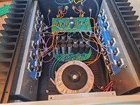
The attached pic is how the amp sits.
Only thing different from the original F5m is that I am trying different IDSS pair JFETs. Also, due to having mosfets in parallel, I am running gate resistors.
So far I like the sound with 6 pairs of output devices per channel pushing around 50 watts. 200mV per device/0.47R. At the moment I am using a 18vac 400va transformer (it is working pretty hard). I just ordered a 800va 22vac transformer which should wake this thing up quite a bit! The extra mosfets darkened and beefed up the soundstage and added the macro texture it was missing which is great. I think it needed it. I had started with 4 pairs of mosfets and the sound was a bit dry being balanced and distortion canceling... Also a bit thin and maybe a bit much on the highs.
Right now at around 50w of bias, I am sitting at 43 degrees on the heatsinks with a mosfet case temperature of around 48C so there is a lot of room for more power.
So after I do some more playing with things then I will eventually draw up some boards for the output stage and finish her up. It sounds really nice so far. I am hoping with the JFETs IDSS being different from N to P, that I am getting the amp to lean towards 2nd harmonic distortion. I may add a P3 type of thing later on.
The power supply is 240,000uF with a gentle CRC filter and a 70uF solen Film on each rail. Both channels share the PS.
The sound is beefy, nice soundstage with airy voices cutting through the mix. If the mix has depth, the sound has depth. I like it quite a bit. I may alter the feedback a bit to see what a different damping factor will do. Also, maybe try different amounts of bias on the JFETs to see what that does.
The attached pic is how the amp sits.
Attachments
There is the potential for lots of power! 🤓
Just looking at your numbers, the bias was 200mV/0.47R = 426mA per device. Dissipation = 2 x 22V x 0.426A = 18.7W per Mosfet pair. So total dissipation = 6 x 18.7W = 112W per channel.
Reading Nelson's F5M writeup, his measurements were based on 1A bias. Your bias of 0.43A per Mosfet pair would probably be a factor in the difference in sound.
Yes, Mr Pass worked those mosfets pretty hard in the F5m which was great with the IRFP140/9140. If I understand correctly, they are effectively 2x240/0240. I think that was a great combination for the F5m. Especially with how he was able to get the 2nd harmonic distortion.
Yes, with the 24vdc rails, it probably has the potential to put out around 90-100 watts into class B. The higher rails will increase that a bit. I don't exactly need that but I have noticed that a little extra rail voltage seems to wake things up a bit.
This is just a test rig at the moment. After I feel like I am done massacring it, I will clean it up quite a bit.
Simple trick. The N channel output has more transconductance than the P, and it being on the negative side will give negative phase 2nd harmonic.
😉
😉
What is the max input voltage for the F5m? My soundraft mixer is rated at Mix Output: +21.5dBu max 75ohm and my Focusrite Scarlett +16dBu max 100ohm. ( thought I would use either/or as pre-amp )
P.S. I did get my amp tuned to 3.5mV offset / ~460mV bias left channel and 6mV offset / ~460mV bias right channel. I'll crank up to 520mV in the future. Speaker test is next.
P.S. I did get my amp tuned to 3.5mV offset / ~460mV bias left channel and 6mV offset / ~460mV bias right channel. I'll crank up to 520mV in the future. Speaker test is next.
^ The article shows ~16.5dB gain => 6.7X
Figure ~20V to clip => ~3V input sensitivity ... maybe if I did it correctly.
Note... that's not RMS.
Figure ~20V to clip => ~3V input sensitivity ... maybe if I did it correctly.
Note... that's not RMS.
I finally got my amp connected to speakers ( cheap bookshelf ) and am getting low volume with lots of static. I have my bias set to ~460mV on both sides, and offset is 7.5mV and 3mV. I go out of my focusrite ( connected TS to balanced TRS out, and used a TS->RCA adapter at the amp ) I tested speakers and input signal with other amp and seems ok. I did'nt want to leave it on too long in case something is wrong.
I did see some noise across R6 on my oScope when I tried using it to set the bias, but the A-B math line on the oscope was too noisy for me to use it. ( 200mV noise range ) I ended up using a 10000count meter instead.
What should I check first?
I did see some noise across R6 on my oScope when I tried using it to set the bias, but the A-B math line on the oscope was too noisy for me to use it. ( 200mV noise range ) I ended up using a 10000count meter instead.
What should I check first?
thanks, i think i found the issue. it's possible i had biased it to .460mV instead of .460V. I got more brave and turned the pots up passed half and pressed a few buttons on the DMMs and I'm confident i now have .460V and ~3mV offset. oops. i'll report back when I am playing music.
Ok, it's playing music and daftpunk RAM sounds very good at low volume. ( on my small infinii bookshelf speakers ) I hear stuff in the song I had not heard before too. ( synth voice)
Ok, it's playing music and daftpunk RAM sounds very good at low volume. ( on my small infinii bookshelf speakers ) I hear stuff in the song I had not heard before too. ( synth voice)
Last edited:
As last build-steps, is there anything to test or check before connecting to 'good' speakers instead of test speakers?
I'll check the DC offset again to ensure it's under 10mV ( on start-up as well ) and keep volume level at under 1/2 for a few hours of use.
I'm thinking of maybe testing using 'REW' software, and/or learning about using my scope with a 1kHz test signal ( function generator ) to visualize when the amp starts clipping. I'm tempted to add an 8ohm resistor between the speaker outputs as a dummy load and connect my scope but not sure of the risk of blowing anything. ( other than ensuring the scope gnd goes to the gnd speaker wire )
Should I consider ensuring the voltage coming out of my mixer/pre-amp is what the amp expects or should I just listen for clipping and adjust volume levels/gains by ear? ( or also doing math to figure out the range of voltage for input ) My current test setup is not ideal since I go from my mac ( volume button in media player ) into the focusrite ( volume button ) and to the amp so not simple knowing what voltage ends up at the amp input. Good problems to have I guess at this point.
DC offset at start isn't as huge a thing as you may imagine. What I look for is a 'smooth' transition from whatever the DC offset may be at startup (ambient temps) and to a "low" offset under temp equilibrium. I watch it it on a DMM.
As long as the amp stays stable under load (test speakers) and I don't hear anything that gives me pause when it's hooked up for 24 hours (give or take, sometimes I'm impatient) then I consider that good to go in hooking it up to more precious drivers.
"Listening" for clipping may be harder than you think. I'd just start with the volume "all the way down" and transition to a comfortable listening level.
What you can do (if you're trying to avoid intentionally clipping) is check the max output on your specific Mac. It's likely below 1Vrms, it may even be below 0V5rms.
Find the gain on your Focusrite ... et voila - you'll know if you can potentially drive the amp to clipping. Mainly, there's likely no need to 'turn it all the way up'.
If you have a two channel scope (you likely do)... What I do is create a "fake differential" with the math function between the two channels for a potentially less precise, but definitely 'safer' way to help ensure I don't blow up my scope or damage my amp, when I want to see the pretty wiggles or square wave performance on a scope.
If you want to use REW to do some basic measurements; it's a lot of fun. Make sure that if you're measuring the output of the amp that you have a voltage divider of some sort (a few options covered in the REW threads) or you'll smoke your Focusrite input stage.
There's likely more that I've forgotten to post... and that's just the way I think it through. There's likely much more / more correct ways to do it.
Have fun!
I had 2 DMMs connected to speaker outputs to monitor DC offset. All of a sudden there was over 100mV DC offset and powered off the amp. I opened the case and noticed one of the secondary spade connectors had come loose from the rectifier.
I'm just curious, would this have damaged the speakers?
Soldering the bridge rectifier to the snubber board reduces the length of the rectifier leads to the point where they cannot be securely connected. I'll have to figure out a way to keep those spade connectors on, maybe I'll solder them if it can be a risk to speakers.
Let’s analyze…
100mV over your 8ohm speakers
0.1V / 8 Ohm = 0.0125A
Which is 0.0012W
I’m pretty sure any loudspeaker out there can handle an extra zero point zero zero one two watts across the input indefinitely.
As for the spades, grab a pliers and tighten the connector a little so it stays on.
100mV over your 8ohm speakers
0.1V / 8 Ohm = 0.0125A
Which is 0.0012W
I’m pretty sure any loudspeaker out there can handle an extra zero point zero zero one two watts across the input indefinitely.
As for the spades, grab a pliers and tighten the connector a little so it stays on.
Another point of reference, I use a AA battery to test polarity of woofers. That's equivalent to 1.5V of DC offset. Never damaged a VC.
If the x-over has a cap in line with the tweeter, the tweeter won't see any DC.
If the x-over has a cap in line with the tweeter, the tweeter won't see any DC.
I'll agree, you need a little slack in the wiring. roboDNA might need to use a wire stretcher... (I'm joking). Maybe something could be relocated (or re-done) just a little to gain some slack / strain relief?
I used pliers to tighten the spade connectors and it seems to have helped. I may have added too much solder to the spade connectors ( belt and suspenders ) to prevent them from being fully inserted. I have shrink tubing around the spade so I don't think it could have shorted anything when it came lose, and if there is no risk for damage to the amp or speakers by them coming lose than I won't belt and suspender them to the rectifier for now.
There is enough wire length already and I added a zip tie around all 4 wires just above the rectifier, but not sure that will help. I think they are on solid enough and should not come loose again.
There is enough wire length already and I added a zip tie around all 4 wires just above the rectifier, but not sure that will help. I think they are on solid enough and should not come loose again.
Or solder the female spade to the terminal? 😮 I think Jim's suggestion will work just fine. There should be a button type of thing on the spade that engages with the terminal on the rectifier. When you take the connector off, push this in so it more firmly engages with the hole on the terminal. That should hopefully keep it from popping off as easily.

- Home
- Amplifiers
- Pass Labs
- F5m kit