Would it make any difference if instead of the 4700uf caps in the power supply I used 15000uf, or 22000uf from EPCOS, same series as the original ones.
B41231A7159M000
B41231A7229M000
these one for reference.
B41231A7159M000
B41231A7229M000
these one for reference.

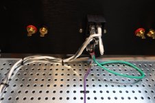
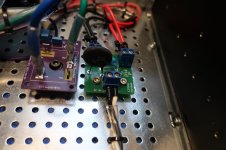
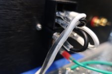
I received the CL-200 bracket from Antek and was able to finally get the wiring done. ( had to re-do connectors to add belt and suspenders ). Should be connecting to DBT in the next couple of days. Since it's my first build ( fingers crossed ), here are the pics to make sure all looks good:
Attachments

^ Nothing that I'd necessarily suggest changing, but a few comments.
I'm not sure what PSU you're running, but a single (don't know if it's an actual CL-60) thermistor in your "soft start / cap module" may get quite toasty and/or be out of its league on 120V mains UNLESS you are running it with the "F5m" PSU that uses the thermistors as both inrush limiting and for the "R" in the CRC. Typically you'd see one across the 'hot' and one across the 'neutral' leads for 120VAC mains.
I'll leave that (potential) concern to others b/c I'm only about 60% sure it's even relevant or accurate, but I wanted to bring it up... just in case... and to learn a bit myself.
- Looks very clean. Attention to detail. 🙂
- As a best practice, the mains earth connection from the PEM should not share any connection to chassis ground. The shield wire from your donut could be shorter and connected to the perforated base plate closer to the donut.
- I like to keep black as hot / white as neutral then follow the black wire through to the primaries with Antek transformers. It's just the way I do it. That isn't even a "best" practice, but I always know that black is hot on the mains AC side of things.
I'm not sure what PSU you're running, but a single (don't know if it's an actual CL-60) thermistor in your "soft start / cap module" may get quite toasty and/or be out of its league on 120V mains UNLESS you are running it with the "F5m" PSU that uses the thermistors as both inrush limiting and for the "R" in the CRC. Typically you'd see one across the 'hot' and one across the 'neutral' leads for 120VAC mains.
I'll leave that (potential) concern to others b/c I'm only about 60% sure it's even relevant or accurate, but I wanted to bring it up... just in case... and to learn a bit myself.
I'm in 120VAC-land and I've had pretty good success using a single CL60 in builds for inrush control. My typical PS uses a 300VA transformer in a CRC configuration with about 170000uF capacitance in total. The fuse is 2.5A slow blow (following the 'VA rating/AC voltage' rule of thumb) and I fortunately have not had any fuse blowing from startup inrush.
The single CL60 does get toasty though.
The single CL60 does get toasty though.
I'm just lurking while I slowly gather parts, but there are a couple things here that have confused me so I thought I'd seek clarification.
So, common advice I see (not specific to this build or even this website) is to configure a star ground and connect everything's that is ground to the one point on the chassis, and then connect that point directly to the PEM mains earth. The way I'm reading your comment suggests I should not be doing that? Or am I misunderstanding? Is it an electrical thing, or a mechanical security of the PEM earth connection to the chassis (i.e. if that connection is its own thing, it's less likely to be accidentally loosened)? The only thing I was ever told was preferred was making sure the earth wire had significantly more slack than live and neutral, so that if the PEM got yanked from the chassis somehow, mains earth would be the last to disconnect.
Also re: the shield wire being shorter, what's the reasoning behind that and how important would you say it is? I ask because my gut feeling is to leave all the transformer wires at their manufactured length (about 20cm) if possible, to avoid stitching myself up if I need to reorient the transformer, or if I need to reuse it in a different build. Cutting it short will also affect the possibility of a star ground arrangement, as it's not close to anything else that needs ground. I'll do it if there's good reason of course. 🙂
As I'm in 240 land and I'm using the F5M supply (500VA with a planned 120000uF) I'm assuming a single CL-60 (or SL22 as in the kit) is fine in my case? Would that change if I were to swap out the supply for one without all the additional thermistors? Or am I generally in the clear as I'm higher voltage lower current?
As an aside/suggestion for future board revisions if any are planned, spacing for terminal blocks on the amp boards and pads for faston headers on the power supply boards would be a nice thing to have. I appreciate the aim of the kit is keeping things simple, but I feel like connection options are good. It's not like you can't just solder wire directly anyway if that's your preference.
As a best practice, the mains earth connection from the PEM should not share any connection to chassis ground. The shield wire from your donut could be shorter and connected to the perforated base plate closer to the donut.
So, common advice I see (not specific to this build or even this website) is to configure a star ground and connect everything's that is ground to the one point on the chassis, and then connect that point directly to the PEM mains earth. The way I'm reading your comment suggests I should not be doing that? Or am I misunderstanding? Is it an electrical thing, or a mechanical security of the PEM earth connection to the chassis (i.e. if that connection is its own thing, it's less likely to be accidentally loosened)? The only thing I was ever told was preferred was making sure the earth wire had significantly more slack than live and neutral, so that if the PEM got yanked from the chassis somehow, mains earth would be the last to disconnect.
Also re: the shield wire being shorter, what's the reasoning behind that and how important would you say it is? I ask because my gut feeling is to leave all the transformer wires at their manufactured length (about 20cm) if possible, to avoid stitching myself up if I need to reorient the transformer, or if I need to reuse it in a different build. Cutting it short will also affect the possibility of a star ground arrangement, as it's not close to anything else that needs ground. I'll do it if there's good reason of course. 🙂
I'm not sure what PSU you're running, but a single (don't know if it's an actual CL-60) thermistor in your "soft start / cap module" may get quite toasty and/or be out of its league on 120V mains UNLESS you are running it with the "F5m" PSU that uses the thermistors as both inrush limiting and for the "R" in the CRC. Typically you'd see one across the 'hot' and one across the 'neutral' leads for 120VAC mains.
As I'm in 240 land and I'm using the F5M supply (500VA with a planned 120000uF) I'm assuming a single CL-60 (or SL22 as in the kit) is fine in my case? Would that change if I were to swap out the supply for one without all the additional thermistors? Or am I generally in the clear as I'm higher voltage lower current?
As an aside/suggestion for future board revisions if any are planned, spacing for terminal blocks on the amp boards and pads for faston headers on the power supply boards would be a nice thing to have. I appreciate the aim of the kit is keeping things simple, but I feel like connection options are good. It's not like you can't just solder wire directly anyway if that's your preference.
Calling all "real" experts to double/triple check below... I'll repeat what I've 'learned', but for the sake of safety, it's best if someone with an actual understanding reviews. We all learn, and I'll take a go, since I was quoted. @twofires - I'm no "expert" in this area. So, wait for someone else to confirm. I got a lot of my information from Rod Elliott's site.
tl;dr - chassis ground will not (always) be at the same potential as "audio ground".
I truly can't / shouldn't specifically comment on the length of the safety earth wire between the PEM and the chassis and any reasoning behind it. That's way out of my league.
Cheers!
A star "ground" is simply connecting a lot of common wires / traces that go back to various boards at the same spot. It is most commonly used for the "Audio" GND.So, common advice I see (not specific to this build or even this website) is to configure a star ground
If chassis ground = audio ground, which in some cases is true - that could be the situation. There are some people that do not use "ground lifts". However, most of the builds you'll see around here (unless they are modified / changed by true experts) will use a ground lift.and connect everything's that is ground to the one point on the chassis,
tl;dr - chassis ground will not (always) be at the same potential as "audio ground".
One thing that holds true is that mains earth "safety" ground MUST be at the same potential as the chassis or very, very close. Any conductive external chassis part that a human can touch MUST have a low impedance path to mains earth. It should be a highly reliable connection. So, it is very commonly recommended (and it may be code in some parts of the world) that the safety earth must not share any other physical connection with the chassis.and then connect that point directly to the PEM mains earth.
I'm only mentioning that the shield wire (ideally) would not share the same physical connection to the chassis as the mains earth connection b/c it is a generally accepted practice. The shield wire needs to be connected to "chassis ground", which is for all practical purposes "mains earth". However, it (ideally) would not share the same physical connection (nut / bolt etc).The way I'm reading your comment suggests I should not be doing that? Or am I misunderstanding? Is it an electrical thing, or a mechanical security of the PEM earth connection to the chassis (i.e. if that connection is its own thing, it's less likely to be accidentally loosened)? The only thing I was ever told was preferred was making sure the earth wire had significantly more slack than live and neutral, so that if the PEM got yanked from the chassis somehow, mains earth would be the last to disconnect.
Also re: the shield wire being shorter, what's the reasoning behind that and how important would you say it is? I ask because my gut feeling is to leave all the transformer wires at their manufactured length (about 20cm) if possible, to avoid stitching myself up if I need to reorient the transformer, or if I need to reuse it in a different build. Cutting it short will also affect the possibility of a star ground arrangement, as it's not close to anything else that needs ground. I'll do it if there's good reason of course. 🙂
I truly can't / shouldn't specifically comment on the length of the safety earth wire between the PEM and the chassis and any reasoning behind it. That's way out of my league.
Cheers!
Last edited:
The only thing I would add i, IF you have a PEM that has metal flanges with holes intended to support screws that hold the PEM in place (ie, NOT a snap-in Mount) then you should use a multimeter to check if the ground pin on the AC entry is connected to the metal flange with what should measure as a short. If so, and ONLY if so, then you already have a ground connection when mounting the OEM with screws. You may, at your discretion, omit the chassis bonding wire to a dedicated chassis ground. But there is no harm, and some may arguably assert that it is safer to always use a separate chassis grounding wire (and I would not disagree).
In you choose to omit the wire to dedicated chassis ground, then use star washers and split washers (or equivalent) to mount the PEM securely to the chassis. A thread locking compound would also be desirable.
This is, as I understand, legal in US. Others who live in other countries must verify their country and local electrical requirements.
^ 100% 

The overarching goal (as I understand it) is:
The overarching goal (as I understand it) is:
One thing that holds true is that mains earth "safety" ground MUST be at the same potential as the chassis or very, very close. Any conductive external chassis part that a human can touch MUST have a low impedance path to mains earth. It should be a highly reliable connection.
Thanks for that folks. For the record I'm absolutely pedantic about Earth pin having a wire to the chassis and all panels measuring 0 ohms back to it, so no dramas there. Not a fan of the 'just torque it and hope for the best' method of panel continuity.
I get what you're saying about that wire having it's own bolt, although I'll have to take a look at how these audio ground lifts are done. I understand that it's to keep ground noise out of the signal, but I'm not sure on how it's usually achieved. Time for me to do some reading. 🙂
I get what you're saying about that wire having it's own bolt, although I'll have to take a look at how these audio ground lifts are done. I understand that it's to keep ground noise out of the signal, but I'm not sure on how it's usually achieved. Time for me to do some reading. 🙂
^ For a few hints (and there are lots of ways, but these are two common ones in FW type amps).I'll have to take a look at how these audio ground lifts are done.
... look for a thermistor that's not in "soft start" role...
... look for a bridge rectifier that doesn't look like it's helping to convert AC to DC.
🙂
As I do it, from rhetoric audio star ground, a wire leads to a circuit element that isolates the audio star ground from the earth ground (which my be to chassis or directly to the ground pin of the PEM) at low voltages and currents, but conducts to earth ground above a certain voltage ir current level.
The circuit element can be a high current diode bridge- 50A would not be unreasonable; parallel but opposite polarity diodes wired with anode to cathode on both ends; or an inrush current limiter. The F5m uses inrush current limiter, but if you look at the schematics for other Pass designs, Mr Pass also uses bridge diodes. Original F5 would be one, as I recall.
The circuit element can be a high current diode bridge- 50A would not be unreasonable; parallel but opposite polarity diodes wired with anode to cathode on both ends; or an inrush current limiter. The F5m uses inrush current limiter, but if you look at the schematics for other Pass designs, Mr Pass also uses bridge diodes. Original F5 would be one, as I recall.
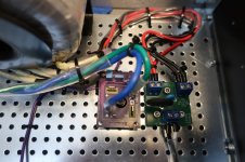
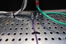
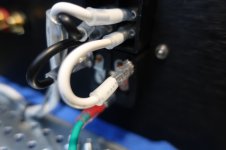
I noticed when I had more than 1 earth ground stacked it was difficult to get the bolt/nut to stay tightened. Moving any of the stacked terminals would loosen the whole thing. Maybe that is why it's not recommended. I left the donut's purple/gnd wire long for now since it's my first build and may need it. I also terminated the donut's purple/gnd just beside the PEM's earth gnd. I used a 'star' lock nut for each earth gnd terminal and it seems solid. I left the PEM's earth gnd long and without zip tie in case someone rips out the PEM. ( will be the last to be ripped out )
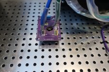
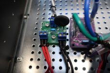
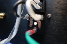
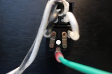
@Zamjazz27 Here is a closeup of the PEM module. Posting here in case anyone else needs to see how to connect it:
@Zamjazz27 Here is a closeup of the PEM module. Posting here in case anyone else needs to see how to connect it:
Attachments
Last edited:
... look for a thermistor that's not in "soft start" role...
Ah, so that'd be that 5th thermistor on the bipolar supply board - the grounded standoff hole of the board is already lifted. Thanks! That solves some issues and creates some others, but I'll wait until I receive my rectifiers and snubber boards etc etc and see what wiring layout I can make work. 🙂
This makes me wonder about whether I need to redo anything on my ACP+ with linear supply build, as that has audio ground straight to chassis ground. But then, it seems to be fine, so maybe I'll just conveniently 'forget' what I did and didn't do with that one. 😅
I really like the Antek CL-200 brackets. But shipping to Europe is 85$.I received the CL-200 bracket from Antek and was able to finally get the wiring done. ( had to re-do connectors to add belt and suspenders ). Should be connecting to DBT in the next couple of days. Since it's my first build ( fingers crossed ), here are the pics to make sure all looks good:
Do we have something similar in Europe too?
Do we have something similar in Europe too?
Some options here: https://www.audiophonics.fr/en/transformers-accessories-c-6356.html
Never tried myself.
Spoke too soon - turns out you may have inadvertently helped me solve a problem with that, so thanks @ItsAllInMyHead!This makes me wonder about whether I need to redo anything on my ACP+ with linear supply build, as that has audio ground straight to chassis ground. But then, it seems to be fine, so maybe I'll just conveniently 'forget' what I did and didn't do with that one. 😅
I was put off by the reviews on those - seems they might be flimsy. Getting a good vertical toroid mount outside of the US isn't easy, I've found. Aus manufacturers don't do them, Toroidy over in Europe doesn't do them, and the crowd who make the Omega Bracket in the US don't seem to want to ship internationally (at least, not to me).Some options here: https://www.audiophonics.fr/en/transformers-accessories-c-6356.html
Never tried myself.
If you have access to a 3D printer, this "transformer seat" using a 130mm pipe strap is a solid and tested method to mount a toroid vertically. The design may need a few tweaks based on your toroid dimensions as it was originally created for Antek 300-400VA (I can assist if tweaks are needed). Just sharing an option that works well and may be more "aquirable" in your neck of the woods. $5 in parts.Getting a good vertical toroid mount outside of the US isn't easy,
Last edited:
This makes me wonder about whether I need to redo anything on my ACP+ with linear supply build, as that has audio ground straight to chassis ground. But then, it seems to be fine, so maybe I'll just conveniently 'forget' what I did and didn't do with that one. 😅
Any time...Spoke too soon - turns out you may have inadvertently helped me solve a problem with that, so thanks @ItsAllInMyHead!
Hopefully what came to mind quickly is that in this 'case' (HA! see what I did there) of the ACP+ Audio GND and "Chassis" ground ARE the same... and the entire circuit has no connection to mains earth. The "PSU" is a two prong SMPS "wall wart" = no connection to mains earth. I am not sure if you put yours in a metal enclosure and/or if you're using the 'bottom PCB' as a ground plane.
The only way I can try and wrap my wee brain around it is...
I start with the (typically) 0VDC reference of the circuit - I call that 'Audio or Signal or Circuit Ground'. Arbitrary reference point.
Then there are sometimes two 'real' grounds.
Chassis - The physical chassis may or may not be at the circuit ground potential. It may or may not be required to be connected to mains earth.
Mains Earth aka Safety earth - the pole stuck in the ground outside your home.
Sometimes all three "grounds" are at the same potential. Sometimes not. Sometimes the only one that matters is circuit ground ... sometimes all three.
If I got 50% of that right, then that's an improvement over last year.

Again... when I put something out there, it's not from a position of expertise. I can share what I think I've learned... and others can add to / correct to help us all out. 🙂
I don't want to complain, but isn't this the F5m thread? Not a power supply thread?
This seems to happen over and over in many of the different threads for the different projects - they get hijacked for very similar, quite repetitive minor power supply connection issues.
Where I'm going is:
I don't have the expertise to do this myself, but there are surely quite a few folks here who do.
Moderators?
6L6?
This seems to happen over and over in many of the different threads for the different projects - they get hijacked for very similar, quite repetitive minor power supply connection issues.
Where I'm going is:
- how about a couple of nice clean new power supply threads? Each starting with some schematics and a basic build guide?
- One about the basic Nelson-style linear power supply and its variations.
- One about switching supplies, probably mostly MeanWell.
I don't have the expertise to do this myself, but there are surely quite a few folks here who do.
Moderators?
6L6?
- Home
- Amplifiers
- Pass Labs
- F5m kit