I don't know of any reason why leaving R17 and J103 connected would cause any problems.Of course, the other reason was the failure to remove R17 and J103. Ouch. Won't make that mistake again
Keeping the parallel 9.1K resistor with R17 only causes the bias through the leds to increase from ~1.3mA to ~6.7mA
Keeping J103 installed only causes Q107 and Q108 to run in class AB instead of class A.
You may need to investigate further as I don't think that was your issue.

Almost all the transistors failed. One cause I suspect is that I didn't have effective grease cover.
Chiptech:
Just to be sure, did you use shoulder washers?
Regards.
I believe the failure was after some time - thermal runaway. He’s using a current limited bench supply.Is it an instant failure or after a while?
Why you haven't used a 💡 tester?
After completing my Wolverine EF-4 as shown in this post I needed to create a nice high end preamp. It should have electronic controlled input selector, volume control and tone control including loudness switch. Furthermore 4 line inputs, a DAC and a bluetooth receiver and a MM/MC phono preamp.
That rather complex project is now almost finished:


I decided to use a ESP32-Devkit processor which has enough power to control all required function including web interface, infrared receiver and a SPI (serial) interface to connect displays, port extender, a serial RAM to store all settings (battery backed up).
The first build was using a relays controlled resistor network. Also the first tone controller was also a relays controlled resistor network in a baxandall circuit. This variant was not so perfect as expected. Slightly different switching times of those relays got sometimes to click noise.
So the final design uses now a MUSES72320 chip for volume control and a NJW1119A chip for tone control. Those chips also need SPI to control their functions. Relays are still used for the input selector, the mono and the loudness switch and also the Tape Monitor/Source switch. Two rotary encoder are used, right for volume/mute, left to control all other functions through menu structure and also to power on/off.
Each input has its own line amp with adjustable gain, I can set sensitivity from -10db to +6db. The ESP32 has also some A/D converters, which I use to emulate VU-meter which helps a lot to set correct gain on all inputs.
I developed a rather extensive web interface and integrated also a infrared remote receiver by software.
Here some screenshot of the provided web pages:


Works over WiFi on any modern browser. For infrared I integrated a old Apple TV remote.
That rather complex project is now almost finished:
I decided to use a ESP32-Devkit processor which has enough power to control all required function including web interface, infrared receiver and a SPI (serial) interface to connect displays, port extender, a serial RAM to store all settings (battery backed up).
The first build was using a relays controlled resistor network. Also the first tone controller was also a relays controlled resistor network in a baxandall circuit. This variant was not so perfect as expected. Slightly different switching times of those relays got sometimes to click noise.
So the final design uses now a MUSES72320 chip for volume control and a NJW1119A chip for tone control. Those chips also need SPI to control their functions. Relays are still used for the input selector, the mono and the loudness switch and also the Tape Monitor/Source switch. Two rotary encoder are used, right for volume/mute, left to control all other functions through menu structure and also to power on/off.
Each input has its own line amp with adjustable gain, I can set sensitivity from -10db to +6db. The ESP32 has also some A/D converters, which I use to emulate VU-meter which helps a lot to set correct gain on all inputs.
I developed a rather extensive web interface and integrated also a infrared remote receiver by software.
Here some screenshot of the provided web pages:
Works over WiFi on any modern browser. For infrared I integrated a old Apple TV remote.
Right. I've checked that and I'm pretty sure they were down tight. I have built several FW amps so I'm familiar with the need to get them attached solidly. But, who knows. I know to make double sure next time.That's a very good point.
I did all my testing with a DC supply at 30A 0.3A for initial testing and 30DCV and 1A for initial power up.Is it an instant failure or after a while?
Why you haven't used a 💡 tester?
The failure occurred at step 20 with the output trans in place.
I was slowly bringing the bias up to ~ 20mV when things went out.
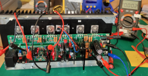
Yeah so Stuart has confirmed no harm done by leaving the temp R17 parallel resistor and J103 in. Thats good.Almost all the transistors failed. One cause I suspect is that I didn't have effective grease cover. I'd appreciate any views on this from the photo.
Of course, the other reason was the failure to remove R17 and J103. Ouch. Won't make that mistake again.
Your problem is still thermal in nature I think, these outputs were not making sufficient contact with the heatsink. This is not just due to "how tight the screws are" - this is due to the transistors not sitting flush with the heatsink, somehow. Either from the screw feeling tight but in fact bottoming out rather than torquing up on the transistor; or the screw being tight, but the transistor has been soldered in a bit short and is raising up somewhere; or the screws thread has been stripped and is not getting the correct torque to get flush to the heatsink. The two center ones would have definitely overheated and shorted IMO.
Yes. a big one and a small one to make sure they were held down tight. See photo. This was shot as I was at step 20 biasing. goal was to get to 40mV and then shut down and put it in position in case to do final biasing.Chiptech:
Just to be sure, did you use shoulder washers?
Regards.
Attachments
Not the big fender washer to spread the clamping force. A shoulder washer would be under that. Those outputs shouldn't need shoulder washers.
Ok, I understand better what to avoid next time. Upon reflection I could see that I didn't get them sitting flush on the heat sink.Yeah so Stuart has confirmed no harm done by leaving the temp R17 parallel resistor and J103 in. Thats good.
Your problem is still thermal in nature I think, these outputs were not making sufficient contact with the heatsink. This is not just due to "how tight the screws are" - this is due to the transistors not sitting flush with the heatsink, somehow. Either from the screw feeling tight but in fact bottoming out rather than torquing up on the transistor; or the screw being tight, but the transistor has been soldered in a bit short and is raising up somewhere; or the screws thread has been stripped and is not getting the correct torque to get flush to the heatsink. The two center ones would have definitely overheated and shorted IMO.
View attachment 1373864
Do you mean the four circled are likely candidates for failure? Looks that way. Do the three in the middle look ok based on grease pattern.
Yes, the circled ones are contacting the heatsink very poorly just looking at those pictures.
you mean shouldn't need fender washers? is there a size, thickness for a shoulder washer you recommend?Not the big fender washer to spread the clamping force. A shoulder washer would be under that. Those outputs shouldn't need shoulder washers.
Chiptech:
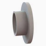
Shoulder washers are usually made of nylon or a similar plastic. The narrow end fits into the MOSFET and the wider end sits on top. Its purpose is to ensure that the bolt used to secure the MOSFET to the heatsink is centered in the MOSFET's mounting hole and does not come into contact with the MOSFET itself. RickRay is probably correct -- it is commonplace now for MOSFETs to have an insulated hole, obviating the need for a shoulder washer. I have plenty of uninsulated MOSFETs that require shoulder washers and wondered if that might be the case for you.
Regards,
Scott
Attachments
I think all of the Output BJTs in the Wolverine BOM do not require shoulder washers as they are plastic topped.
Drivers are different, onsemi drivers need shoulder washers for sure.
@Chiptech - check your drivers are also not overheating and are nice and flush with their heatsink.
Drivers are different, onsemi drivers need shoulder washers for sure.
@Chiptech - check your drivers are also not overheating and are nice and flush with their heatsink.
Scott, thanks for the info on shoulder washers.
They would not fit in my BJTs as mainframe points out.
Do I not use a washer at all? Use a smaller one?
Nice and flush is my new north star. Live and learn
They would not fit in my BJTs as mainframe points out.
Do I not use a washer at all? Use a smaller one?
Nice and flush is my new north star. Live and learn
@Chiptech, are all your heatsink tapped holes absolutely vertical? The circled mounting photos seems to show otherwise with the uneven goo distribution.
A drill press is strongly recommended and great care is needed for hand tapping. One of the reasons for using the large Belleville washer is that it can accommodate small amounts of offset angle but only when there are no other washers used AND when it is mounted the correct way up.
A drill press is strongly recommended and great care is needed for hand tapping. One of the reasons for using the large Belleville washer is that it can accommodate small amounts of offset angle but only when there are no other washers used AND when it is mounted the correct way up.
- Home
- Amplifiers
- Solid State
- DIY Class A/B Amp The "Wolverine" build thread