Stuart,I don't know of any reason why leaving R17 and J103 connected would cause any problems.
Keeping the parallel 9.1K resistor with R17 only causes the bias through the leds to increase from ~1.3mA to ~6.7mA
Keeping J103 installed only causes Q107 and Q108 to run in class AB instead of class A.
You may need to investigate further as I don't think that was your issue.
Thanks for this information. If R17 and J103 are ruled out, I think it's trouble with how I installed my output transistors.
When I'm ready to test the IPS board, I would like to use the setup from your video. Can you tell me the name of the Breadboard you used.
@Chiptech those big shiny things that look like flat washers that you used to attach your transistors to the heatsink are Belleville Washers if you got the case hardware from DIYA. Their shape is very slightly conical. You mount them with the cone pointing up. The cone flattens slightly when it is screwed down stretching the outer diameter. The result is a lever-couple between the outer diameter and the centre screw with enormous mechanical advantage to prevent movement/rotation and also a large/wide contact area holding the transistor against the heatsink.
If you used them upside down I don't think there there is a problem other than less than ideal attach pressure.

If you used them upside down I don't think there there is a problem other than less than ideal attach pressure.

Hi Chip,Johno, I'm using a heat sink I've repurposed from a previous Pass F6 diy build.
Drilling holes is above my pay grade.
I will check the vertical on each hole.
I have ordered a set of Belleville washers.
Thanks,
Chip
Just as a side note;
You can use a deburring tool or countersink tool by hand just to take off the slight lip on the tapped holes.
Alternatively
If you have a sharp drill bit a few sizes larger than the drilled hole you can by hand place it over the hole and twist it with your fingers to de-burr the tapped holes for each transistor.
You just need to make sure there is nothing sitting proud (above) the heatsink surface so only a very slight amount of force is needed to clean up the holes.
If you dont fix this it will be very difficult to get your amplifier builds working.
Two reasons:
1. Thermal problems due to transistors not having a good thermal bond with the insulator and then heatsink.
2. "Swarf" or small metal bits from cutting holes threads etc can pierce the insulators causing a dead short between the heatsink and transistor.
I hope this is useful for you.
It will be great to see you get this working.
- Dan
Not a big deal at all, and I don't want to derail the topic, but where did you get this information, please? It would be very helpful for me to know. The washers provided with the "back panel parts kits" from the diyAudio store should be simple fender washers, not Belleville. Did you receive Belleville washers in a kit? Was it within the last 4 or 5 years?those big shiny things that look like flat washers that you used to attach your transistors to the heatsink are Belleville Washers if you got the case hardware from DIYA
Excerpt copied from page linked.
- 24 fender washers for MOSFET / Diode mounting
I have the same questions. I checked the store and didn't see any offerings. I've ordered a set from Amazon:
https://www.amazon.com/gp/product/B07CSQDS7F/ref=ppx_yo_dt_b_asin_title_o00_s00?ie=UTF8&psc=
1 but now I'm uncertain they are the correct type.
Hilitchi 215-Pcs [M3 - M12] Metric 304 Stainless Steel Belleville Spring Washer Assortment Set
https://www.amazon.com/gp/product/B07CSQDS7F/ref=ppx_yo_dt_b_asin_title_o00_s00?ie=UTF8&psc=
1 but now I'm uncertain they are the correct type.
I'm not sure whether Belleville washers will help this case or not. They certainly won't hurt, most builders use them. If your heatsinks were machine drilled (i.e. you have a DIY audio deluxe chassis) the holes should be nice and vertical. Belleville washers will help with minor hole direction errors.
Either way, (this isn't pointing at Chiptech directly) the:
1. Output transistors should not have been soldered into the PCB without first ensuring they were nice and flat on the heatsink, screwed down enough so that they won't wiggle when tested gently with your index finger and thumb, but not cranked down so much you strip your threads. Do a visual to actually look for gaps under the transistors. The insulating pad (sil or mica+grease) should be installed but no grease applied at this point, because if it wasn't, you are adjusting the Z height when you go and later add this pad, resulting in possible gaps under the transistors!
2. Also ensure the amp PCB was installed nice and flat before soldering in the outputs, with no gaps under any of the PCB standoffs - above or below the standoff. So, your PCB is 10mm* above the heatsink at all corners and midpoints.
If the Output transistors were not flush with the heatsink when soldered into the PCB, or the PCB was incorrectly tightened to the standoffs during the Output transistor soldering process and then later tightened down correctly, IMO no amount of Belleville washers are going to save you.
Heck, even the output transistors back plate could be bent if they've been rolling around a parts bin for years. I'm into the weeds now though, highly unlikely.
*depending on your chosen standoff height for your amp boards, and only applicable to parallel mounted to heatsink boards.
Mainframe,
This is very useful. This is worth diving down on because we have a lot invested when its time to fire up the outputs. Thanks for taking the time to write it up.
This is my postmortem so I can learn and not repeat what doesn't work.
I do have a diyaudio store 4U case and heat sinks. You will not find me drilling holes.
I did not take the job of placing the heat sinks seriously enough.
I did fit the transistors on the heat sink without the insulator pads because step 18. c said not to do that.
I didn't do a visual check, especially to look under the board [see photo]. When I did look afterwards, I could see several that were not placed solidly. I will add this step next time.
I did not make sure the board was 10mm above and level. Currently my board is ~8mm.
Attachments

This right here ^ - this is going to cause problems! I can also see the gaps under the output transistors.
Chip - it doesn't NEED to be 10mm - it can be between 8-10mm according to the build guide. But it needs to be level all around. Those standoffs need their male threads trimmed so they wind all the way in, flush with the heatsink. Your standoffs may be too short if you are currently at 8mm.

What is the height of the standoffs you have there? (not including the male thread).
You will need to remove and reinstall the output transistors (or install fresh ones) once you have corrected the PCB standoffs, because leaving them as is will force the PCB to sit crooked once the standoffs Z height is changed, again they wont get flush.
Chip - it doesn't NEED to be 10mm - it can be between 8-10mm according to the build guide. But it needs to be level all around. Those standoffs need their male threads trimmed so they wind all the way in, flush with the heatsink. Your standoffs may be too short if you are currently at 8mm.
What is the height of the standoffs you have there? (not including the male thread).
You will need to remove and reinstall the output transistors (or install fresh ones) once you have corrected the PCB standoffs, because leaving them as is will force the PCB to sit crooked once the standoffs Z height is changed, again they wont get flush.
Last edited:
It would be over 10 years nowWas it within the last 4 or 5 years?
Mainframe thanks for taking the time to detail what is involved in getting outputs on heat sinks correctly installed.
Let's do the math.
I measure the hole in the heat sink at 7mm
Screw length on my standoff is 6mm
The standoff from the heat sink up is 8mm
Not sure why I can't get the standoffs to be flush with the heat sink. All the standoffs, in place, in the heat sink measure 9mm. They should work.
All of my transistors blew on both boards so I will be replacing them. I'm going to build new boards, so I don't have to worry about missing a bad part.
I did get these boards to initially light up and be working under reduced power.
Now that I better understand how to install the outputs correctly, I will get underway next week.
See slide 4 in this image - the usable tapped length of a blind hole does not go to the bottom of the hole. Your 6mm male thread on your standoff will probably only get 5mm max down into a 7mm deep hole.

You are correct though, if all your standoffs are an even 9mm - and you confirm this by measuring the distance between the installed PCB and the heatsink at 4 corners and 2 midway points - you shouldn't have issues installing the output transistors
Not sure why I can't get the standoffs to be flush with the heat sink. All the standoffs, in place, in the heat sink measure 9mm. They should work.
You are correct though, if all your standoffs are an even 9mm - and you confirm this by measuring the distance between the installed PCB and the heatsink at 4 corners and 2 midway points - you shouldn't have issues installing the output transistors
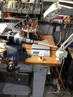
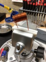
Ok folks, here is what I came up with for winding the inductors. Based on mainframe99's input I used a variable speed drill with a 0.5" dowel (12.7mm) and 16 AWG magnet wire. I drilled a hole using a #52 drill straight through the dowel close to where the dowel is being held by the drill chuck. Then I inserted the end of the magnet wire into the dowel, but not all the way through it. By putting tension on the other end of the magnet wire and running the drill at it's slowest speed I was able to wind the wire. I need to measure the inductance using my Peak Atlas LCR meter and cut it to the proper length. It's not perfect, but it looks a heck of a lot better than my first attempt.
I'm hoping this helps someone who may be struggling with forming the inductors....
John
I'm hoping this helps someone who may be struggling with forming the inductors....
John
Attachments
You can unwind the inductor and rewind it if you want to try again. Just grab one end and pull. Mine come out better on the second try normally as the wire starts out straighter after unwinding it.
@Chiptech please confirm that you bent the legs of the output transistors at 90° then assembled the output transistors to the heatsink then placed the amplifier boards over the legs of the output transistors. Then finally soldered the outputs to the boards.
Also you need to ensure the large washers do not touch the edge of the pcb. As the full rail voltage passes close to the top edge of the pcb.
Also you need to ensure the large washers do not touch the edge of the pcb. As the full rail voltage passes close to the top edge of the pcb.
First of all, put on a flexible work glove, do not step on the machine for winding ... try with your hands with the glove to rotate with tension the wire and with force to the previous one winding so that each winding applies to the previous one ...Ok folks, here is what I came up with for winding the inductors.
I did bend them at 90, though next time I will measure it.@Chiptech please confirm that you bent the legs of the output transistors at 90° then assembled the output transistors to the heatsink then placed the amplifier boards over the legs of the output transistors. Then finally soldered the outputs to the boards.
Also you need to ensure the large washers do not touch the edge of the pcb. As the full rail voltage passes close to the top edge of the pcb.
The rest I did as you describe. I have experience with this step while building several FW amps. Not saying I'm deeply experienced.
Given my track record with grease, could I use Keratherm transistor insulators under the outputs and no grease? I know the guide says to use mica and grease, but just asking.
I have an "old" chassie that Im̀ going to use,inside of it is 2 cap mulriplier pcb https://www.etsy.com/se-en/listing/...66&click_sum=a5950256&ref=shop_home_active_34
could it be used with class a/b amp? or is it better to use a CRC?I realize in the case of the capmultiplier I am going to have to change some elyts, Iḿ going for the 2x42 ac verision.
could it be used with class a/b amp? or is it better to use a CRC?I realize in the case of the capmultiplier I am going to have to change some elyts, Iḿ going for the 2x42 ac verision.
You can use silicone pad insulators (keratherm as you say, is a brand name of such) but at a micro scale these will be even less forgiving to flatness imperfections than mica+grease.
With any well designed class AB amplifier cap multipliers and CRC supplies just cause excessive power supply droop with no real advantage. The PSRR of the input stage does a much better job of removing any hum than either of those supply types would.I have an "old" chassie that Im̀ going to use,inside of it is 2 cap mulriplier pcb https://www.etsy.com/se-en/listing/699792666/smooth-like-buttah-slb-class-a-psu?click_key=5373be564a4a8d8a5b81711098b2b0a4c3f61269:699792666&click_sum=a5950256&ref=shop_home_active_34
could it be used with class a/b amp? or is it better to use a CRC?I realize in the case of the capmultiplier I am going to have to change some elyts, Iḿ going for the 2x42 ac verision.
- Home
- Amplifiers
- Solid State
- DIY Class A/B Amp The "Wolverine" build thread