That’s HOT…😉
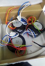
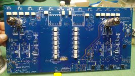
small pcb shown bellow; there are 3 small Donuts wired to
when power switch is flipped, Donut No.1 (heating and logic) is connected directly to mains, so tube heating regs are getting juice and tubes are heating. In same time Arduino Is Alive!, there is (already famous) Greeting screen, written with N. Tesla handwriting font, shown for 10sec, then switching to "Heating tubes..." screen for 20 secs more; then Arduino is powering SState relay, giving mains to Donut No.2 and Donut No.3; 20 secs later ("Heating tubes..." shown all the time), Arduino is energizing all input relays, Volume relays and also "output mute" relay (practically un-muting), flipping in same time to functional screen
All in all, from switch flip to singing , there is a pause of 10+20+20=50secs (first 30 just heating, then 20 unnecessary long to all things to settle), pretty much same as if you're powering preamp in the morning, to be able to watch 20.00 Clock News

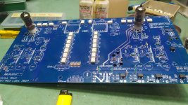
Donut No.1: 30VA, 24Vct 650mA (TFT, Logic, relays), 9V 1A6 (heaters)
Donut No.2: 30VA, 56Vct, 56Vct ....... is having separate secondaries for each channel, for +/-25Vdc rails; positive is shunt regulated, negative is simple LM337, good enough because there is "just" CCS on negative rail, giving darn good isolation per se; reminder - last pic in #1944
Donut No.3: 20VA, 100V, 100V......... is having separate secondaries for each channel, for shunt regulated +90Vdc rail
difference between Tube-Mos buffer and JFets buffer being not just addition of 2 PSUs per channel (heater, HiVoltage) but also Plethora of details needing attention ........ outcome pretty much as expected - I can live with either/both of them ..... but major bingo is sheer intellectual enjoyment I had while developing it as full package

So cool. Have any specific links to your transformers of choice? Assuming some of us crazies are already making plans before the cake is even fully baked..... Antek is a bit lacking in options on the US side of the realm.
didn't even think of ready-made Donuts; "my" custom made ones will be included in kits ..... that's simplest way of avoiding bunch of headaches
though, not going to include signal iron, no logic in importing them then exporting, that would just increase cost of entire package
though, not going to include signal iron, no logic in importing them then exporting, that would just increase cost of entire package
of choice?
bolts are M4, perspective info
Attachments
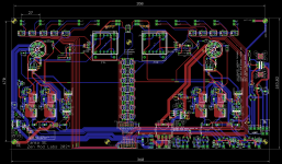
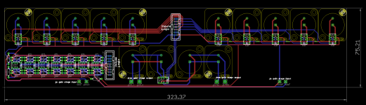
was thinking how to increase useful area of already big Motherboards ......... there is no other way than to move something out ........
anyhow, main idea with Motherboard approach was to avoid messy wiring and zillion-small-pcbs-connected-with-zillion-wires
so, Lucida Intervalla, or what?
lazy Sunday fun
one of these days will make one strictly for RCA, even if that one is less likely to be needed
anyhow, main idea with Motherboard approach was to avoid messy wiring and zillion-small-pcbs-connected-with-zillion-wires
so, Lucida Intervalla, or what?
lazy Sunday fun
one of these days will make one strictly for RCA, even if that one is less likely to be needed
Attachments
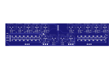

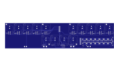
With slave boards ?was thinking how to increase useful area of already big Motherboards
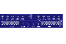
moving selector and volume to back plate pcb
resorting to straight solder pin Neutrik XLRs and - for case with RCA - regular "cup" Neutrik RCA, so shown pcb soldered ditto to connectors, no other fixing points needed
(though, for RCA, will include screw holes, to mount pcb practically on long screws fixing RCAs)
when all that moved from main big pcb, there is even less wires from back plate of preamp to main pcb, while huge area on main pcb freed for all shenanigans

Niamh is tubed without any Iron in signal chain, and only SE; dunno how I could pack Bal and all paraphernalia in existing format of 183.8*360mm; only if I decide to deepen it (230 maybe?)..... counting it already demands 350deep case
ZM,
Does this solution ("selector and volume to back plate pcb") allows for a Niamh (Bal)?
ZM. I think this is incredible—WAY beyond any expectations I might have. Love the HUGE PCB, personally.
ZM,
Does this solution ("selector and volume to back plate pcb") allows for a Niamh (Bal)?
cheeky guy

yeah, that was one of the reasons ........
When you send out these kits—sign the PCB in white paintpen—"ZM Omnibeyond".
There will be no doubt then.
There will be no doubt then.
Can't do that
There is Only One, and I can just cruse under critical level of imposter, or I would be even more under disgrace
in a meantime..............

There is Only One, and I can just cruse under critical level of imposter, or I would be even more under disgrace
in a meantime..............
Dear OmniZM,
how far have you gotten with repetitive work?
Are your feets already tapping to the rhythm of the balanced Tanka?
how far have you gotten with repetitive work?
Are your feets already tapping to the rhythm of the balanced Tanka?
not yet
as always, ZM Omni, working on several things in same time, finishing even less
need to order Donuts, so it'll be few weeks time
as always, ZM Omni, working on several things in same time, finishing even less
need to order Donuts, so it'll be few weeks time
- Home
- Amplifiers
- Pass Labs
- What's wrong with the kiss, boy?