What is the amperage reported on the outputs on the Rigol? (i.e. is the supply current limiting, even with the Bias at 0?)
Your measured voltage across TP101 and TP102 is 0.00V?
Your measured voltage across TP101 and TP102 is 0.00V?
Last edited:
Ah, you should have an email with the link to the build guide and BOM if you have purchased the PCBs. If not, send a follow up PM to whoever you dealt with getting the PCBs. Check junk email too. Sometime dropbox links get junked.Thats what I meant,I havent yet gotten my pcbs so I dont have access to the build guide..
Hi John,Hi Guys,
I am just completing the build of the first power board, EF3-4 V 4.0. I am mounting drivers Q107 and Q108 under the board so that they lie on the heatsink. I noticed that my MJE15032G and MJE15033G drivers have full metal backs. This means I need to source shoulder washers front and back and use thermal pads to isolate them. Those drivers are in a TO-220-3 package. Looking on Mouser it looks like you have to measure the hole in the transistor in order to source the right one, correct? Do you use two identical washers for the front and back of each transistor?
Many thanks,
John
I'm not sure what the exact part numbers for the TO-220 insulator and washer are. I just used these from my local "radio shack" and they worked well. Hope you can find something local. https://www.jaycar.co.nz/to-220-silicone-rubber-insulating-kit-pack-of-4/p/HP1176
Heres an image I pulled from the web - you only use one washer so the screw holding the transistor to the pad does not contact the metal heatsink of the transistor
In this case you ignore 3, 6 and 4, because your screw (5) is going into a threaded hole in the heatsink. You just need 1x nylon shoulder washer (1), the screw (5) and the thermal pad (5)
Last edited:
Use 6 or 8 amp rail fuses. 6 for most cases, 8 if you often listen loud or parties, 10 if you are driving horribly inefficient speakers (lower than 84dB) at party levels.Step 20.k says to refer to sheet 2 of the BOM to determine correct fuses to be used with full power.
My Cobra SMPS is 64DCV out.
On sheet 2, I don't see anything that provides guidance for correct fuse amperage.
Can someone clarify what I'm missing.
Thanks
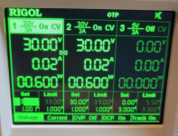
Not sure on your first question. I set the Rigol for 1A. And the limit at 1A.What is the amperage reported on the outputs on the Rigol? (i.e. is the supply current limiting, even with the Bias at 0?)
Your measured voltage across TP101 and TP102 is 0.00V?
TP101 to TP102 reads 0.0mV with R109 set at max resistance.
The power supply should read 3 things per rail (I could be wrong I'm not familiar with all models) - Voltage, Current being delivered and current limit or wattage. The current may show two lines or be selectable - the actual current being delivered, and the current limit.
The current limit is not the same as the current being delivered in real time.
This is so you can see the current increase or decrease as you control a load, and then you can tell if the rail is slamming into the current limit.
The current limit is not the same as the current being delivered in real time.
This is so you can see the current increase or decrease as you control a load, and then you can tell if the rail is slamming into the current limit.
A little more progress today. Resistors in…


Okay the boards only drawing 20mA a rail, that's good. nothings shorting and slamming the PSU into the current limits. I suspect the CCS cannot get its full current at 30V rails due to the addition of the output transistors - but would need comment from more experienced builders. Is the resistor still installed parallel across R17? This should have only been removed for when you go to final rail voltage.These are the readings with R11 maxed out and getting 2.9V
R109 still set at max resistance.
I'd try turning the R109 bias circuit up and monitoring the bias voltage and the PSU current being delivered on each rail to see the bias circuit "working", then bring it back down and go to full voltage 64V test. If nothings shorting and smoking, or pulling the PSU into the current limits at 30V, 64V should be fine.
As I get closer to being able to test my boards I'll need to buy a DC power supply. I don't currently have one. I'm thinking about buying a cheap 30v 10a one from amazon.
Question: Will I need two of these for the positive and negative rail? Any thoughts on weather I should invest in a 60v or 120v version?
Thanks for any advise here. Appreciate it.
Question: Will I need two of these for the positive and negative rail? Any thoughts on weather I should invest in a 60v or 120v version?
Thanks for any advise here. Appreciate it.
I recommend a Rigol DP832. It has two 30V power supplies that you can link to provide V+ V- and Gnd to an amp board.
It also allows you to fix voltage and amp limits to prevent damage to your board. I bought a new one on eBay for $400.00, and you can find used ones. Also good documentation. I bought a cheap PS on Amazon and returned it.
It also allows you to fix voltage and amp limits to prevent damage to your board. I bought a new one on eBay for $400.00, and you can find used ones. Also good documentation. I bought a cheap PS on Amazon and returned it.
Attachments

I think that might be a little too expensive for me unfortunately. Thanks for the recommendation though. 
A bench supply is a nice option but isn't really necessary. People have been starting up new amps with variacs or bulb limitters for a long time.
If you have a spare tranny and caps lying around from other projects or junk amps, I would recommend grabbing a Variac and making up your own DC supply that you can control with the variac. I’m not sure what a variac goes for in the northern hemisphere but mine was only a hundred and something down here on sale. You can even run the DC rails through some old DC ammeters to give you a current readout.
If you are using a linear supply - SMPS YMMV because one of both of these could trigger the protection circuit(s):
Both of these will "show" you if you have a problem before you cause any real damage. Of course use your DMM to check for any shorts prior to strat-up.
Once these have been used to confirm no issues, turn down the bias pot 4-5 turns and remove the current limiter (DBT or Resistors) out of the chain and "go fo it" - should be a non-event and you can set final bias and offset, let it burn-in and sit back and enjoy some music.
- Use a DBT (dim bulb tester (can make one for $20) - start with 40W, then 60W, then 150w bulbs
- Use a couple 1r 5-10w resistors in line with the power rails and use a DMM to measure the voltage across those resistors to see the current draw
Both of these will "show" you if you have a problem before you cause any real damage. Of course use your DMM to check for any shorts prior to strat-up.
Once these have been used to confirm no issues, turn down the bias pot 4-5 turns and remove the current limiter (DBT or Resistors) out of the chain and "go fo it" - should be a non-event and you can set final bias and offset, let it burn-in and sit back and enjoy some music.
I have moved my first board to full power from the Cobra SMPS.
Leds good.
R11 5V good and steady
R25 0 mV
R109 not stable bias point.
I set R109 at 40mV but it started to climb as far as 70mV in a few minutes before I adjusted it back down. At that point it started to decline and over 20 minutes it declined to ~21.6mV.
The heat sink seemed appropriately warm across the sink.
I don't have the heat sink in close to the amp box, nor did I put a top on it to "cook."
I achieved 20mV while using my DC power supply set at 30DCV and it appeared to be steady.
Appreciate the help to sort this out.
Thanks
Last edited:
- Home
- Amplifiers
- Solid State
- DIY Class A/B Amp The "Wolverine" build thread