
Nope , https://audioxpress.com/article/you...att-class-a-amplifier-part-1-amplifier-design(Probably a bit beyond DIYA at this stage)
readily available for DIY...
OS
What would be the improvement ? Lower THD ? More efficient (Hypex Nilai500DIY) , B Putzey got 2ppm @ 200W 94% eff.I'll stick with wolverine for the next 10 or so years I'd say
We are now at an inflection point in audio , at least for the electronics. 2 PPM Topping DAC , 2 PPM amp ?
The only thing left is the speaker at mostly 1% , some Heil ribbon tweet's can get <.1% , then the room acoustics - nada.
Maybe a chip in the brain to direct convert the electronics to perceived audio.😉
OS
Well, I'll be! Thats neat. That's fresh too (aug '24). Is that one of the DIY audio members designs? Still, it's a heck of a lot of work, and not as objectively performant as the best 'traditional' style we have here, wouldn't you say?Nope , https://audioxpress.com/article/you...att-class-a-amplifier-part-1-amplifier-design
readily available for DIY...
OS
I agree - it does seem a bit pointless when the speakers and room are far more of the problem.What would be the improvement ? Lower THD ? More efficient (Hypex Nilai500DIY) , B Putzey got 2ppm @ 200W 94% eff.
We are now at an inflection point in audio , at least for the electronics. 2 PPM Topping DAC , 2 PPM amp ?
The only thing left is the speaker at mostly 1% , some Heil ribbon tweet's can get <.1% , then the room acoustics - nada.
Maybe a chip in the brain to direct convert the electronics to perceived audio.😉
OS
Elon Musk - Neuralink Hi-Fi coming to a lab near you soon! Pay 18.99 a month for full Ad and politic-free playback!
Looking forward to hearing the Wolverine,You are about have the equivalent of a "benchmark AB2" (Google it) . actually the Wolverine beats it.
"benchmark" uses a 1200W SMPS that is integrated - only difference. Benchmark does 1-2ppm , Wolverine can go sub ppm.
Price is the big difference. Benchmark goes for $3500 !
DIY rules !
OS
You won't hear it , "wire with gain"....Looking forward to hearing the Wolverine,
I have successfully completed Initial power up.
I adjusted R11 to 5V DC.
I adjusted TP-105 V+ and TP-106 V- to 1.5V
I adjusted R109 to 1.15V DC.
I was using a Rigol DC Reg Supply.
I have now installed the power transistors and am ready for section 20: powering up the output transistors.
Two questions. Upon completing the initial power up I turned R109 back all the way.
1. I did not reduce R11, so it is still set at 5V. Is that an error and do I need to remove the output transistors and turn down R11?
2. I am using a Cobra SMPS and my understanding it that I can't use a Variac with it. Should I proceed?
If not, if the risk is too great, my back up is to install the 64DCV regular PSU and use that to bias my amp boards.
I appreciate guidance here. I've come too far to mess it up now.
And thanks,
Still hoping to get some feedback.I have successfully completed Initial power up.
I adjusted R11 to 5V DC.
I adjusted TP-105 V+ and TP-106 V- to 1.5V
I adjusted R109 to 1.15V DC.
I was using a Rigol DC Reg Supply.
I have now installed the power transistors and am ready for section 20: powering up the output transistors.
Two questions. Upon completing the initial power up I turned R109 back all the way.
1. I did not reduce R11, so it is still set at 5V. Is that an error and do I need to remove the output transistors and turn down R11?
2. I am using a Cobra SMPS and my understanding it that I can't use a Variac with it. Should I proceed?
If not, if the risk is too great, my back up is to install the 64DCV regular PSU and use that to bias my amp boards.
I appreciate guidance here. I've come too far to mess it up now.
And thanks,
An additional thought. If I do need to dial down the R11 setting [5V DC], can I leave the output transistors in and use my DC supply to power it up enough to reduce R11, without creating any other issues? That would limit the DCV to 30DCV.
FWIW - I think you are fine. I would only suggest once you have everything connected, to check for shorts, + to GND, - to GND and all outputs to the heatsink. Then at power up, even if R11 goes over 5V, it will be a few mV, which won't blow anything, and you can dial it back, the most important is the Bias, and if you have taken the precautcion to dial it back you will be fine.
If you are super cautious, you could always put a 1r (5-10w) resistor in line from the SMPS to the amp board, which will limit the current and burn up those resistors if you do have a bad issue - again, your DMM should help you know that before power-on, so it's up to you.
I went from +/-36V on my bench to +/-68V in the chassis and turned the bias pot down 5-6 full turns and it was only a little high at start-up and the 5V was high like 6V, but a half turn and it was within spec.. Testing on the bench and moving to chassis, went uneventful, thanks to the good design.
bullittstang,
Thanks very much. I will proceed with CAUTION.
Where would I put the 1ohm 5+ watt resistor, between the V+ wire from the Cobra to the V+ on the board. Or V-?
Thanks very much. I will proceed with CAUTION.
Where would I put the 1ohm 5+ watt resistor, between the V+ wire from the Cobra to the V+ on the board. Or V-?
Last edited:
Dual differential front end along with dual VAS is an improvement somewhat similar to using Jfets at the inputs.
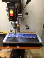
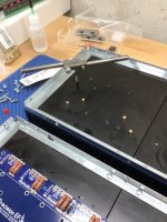
Just a progress report. Tonight was drill and tap the diyaudio 5U heatsinks for a couple of extra standoffs and for Q103, Q107 and Q108 which will go under the pcb (I have the EF3-4 V. 4.0 boards). I bought 100 brass 10mm standoffs from Amazon for less than $8, but like Daniel the 6mm threaded area was too long. So I took his advice and used my Dremel to shorten them. Threading the nut on before you do this is essential as it deburrs the cut threads. They appear to fit perfectly. Just follow Daniel's procedure for marking the position using the pcb as a template. Use Tap Magic or similar oil. Make sure to use a 2.5mm drill for a 3mm tap. Take it easy when tapping.....those standoffs are soft brass...and use oil.
Best to all,
John
Best to all,
John
Attachments
You need two resistors , one resistor for each rail (1- positive (SMPS to amp) and 1-negative rail (SMPS to amp))bullittstang,
Thanks very much. I will proceed with CAUTION.
Where would I put the 1ohm 5+ watt resistor, between the V+ wire from the Cobra to the V+ on the board. Or V-?
1. No, you do not need to turn down R11 after completing initial testing (step 17) without output transistors. This will remain at or around 5V (it will drift a little as temperatures change) so its fine to leave it and tweak it later. (It would have been put in the build guide if this was a requirement.)I have successfully completed Initial power up.
I adjusted R11 to 5V DC.
I adjusted TP-105 V+ and TP-106 V- to 1.5V
I adjusted R109 to 1.15V DC.
I was using a Rigol DC Reg Supply.
I have now installed the power transistors and am ready for section 20: powering up the output transistors.
Two questions. Upon completing the initial power up I turned R109 back all the way.
1. I did not reduce R11, so it is still set at 5V. Is that an error and do I need to remove the output transistors and turn down R11?
2. I am using a Cobra SMPS and my understanding it that I can't use a Variac with it. Should I proceed?
If not, if the risk is too great, my back up is to install the 64DCV regular PSU and use that to bias my amp boards.
I appreciate guidance here. I've come too far to mess it up now.
And thanks,
2. No, you should not use a Variac on the Cobra, it will cause undesirable behavior and may blow its internal fuse or output protections.
If it is your first time, step 20 must be performed with the same "TESTING" power supply you used for step 17, ideally 30V. If you have performed step 17 with full rail voltages, I hope you first removed the temporary resistor placed across R17 (or never had installed). You may be okay to go full rail voltage at step 20 if step 17 passed full rail voltage, just be sure to have the correct fuses installed as step 20 A, and you absolutely must have passed step 19, and also checked all transistor legs for no shorts to PCB ground or the heatsink.
(The cobras output SC protection is faster than the 2A fuses if there is a rail-ground or rail-rail short anyway, I've ahem tested this)
Remember, at step 20, you are measuring bias voltage at TP's 101 and 102, NOT R111A and R111B. The build guide unintentionally confuses the reader here by saying "as done in the initial test procedure", potentially leading the builder to put the probes BACK at R111A and R111B, which is incorrect.
I adjusted TP-105 V+ and TP-106 V- to 1.5V
P.S> how did you do this? these values aren't adjustable, but they do vary slightly with rail voltage, which leads me to believe you did manage to complete step 17 with full rail voltage?
Last edited:
This fuse is only protecting the internal AC line cable from shorts to the chassis running from the IEC socket to the cobras AC input. Your IEC socket should be a 3 pin, with the earth connected directly to the chassis.Can I ask what fuse rating you use in the IEC for the Cobra?
The cobra is capable of pulling 1900W peaks (1200W sustained), and your American sockets are capable of ~1800W sustained, so this fuse should be 10-12A (15A at the absolute maximum) - provided the cable gauge you used from IEC to cobra can sustain this also. Otherwise the fuse must be sized to protect the maximum the cable gauge can handle. The cobra has a fuse protecting anything beyond its AC inputs from shorting on its PCB, and also has protections built in for its output rails.
If, for some reason, you used skinny *** cable from the IEC socket to the cobra than can only handle 5A, you really should have this fuse at 5A. (yes i know the short distance means the skinny *** cable can probably handle more but let's keep it simple and safe)
Last edited:
This shouldn't be necessary, especially if successful with a 30V test supply at stage 20.bullittstang,
Thanks very much. I will proceed with CAUTION.
Where would I put the 1ohm 5+ watt resistor, between the V+ wire from the Cobra to the V+ on the board. Or V-?
Wrong pinout. Could make it work maybe. Wouldn't use big rail voltages. SOA a bit low.ksa1220a is obsolete so I guess that's the reason for not mentioning it in BOM as it has better specs than 2sa1837 and at higher voltages has better specs than any other driver transistor mentioned in BOM. I do not like mje150xx transistors as these are slow while drivers should be fast. I'll probably use KSA/KSC in my EF3-4. In my EF3-3 I'm using 2sa1859a/sc4883a. Haven't yet put these finished boards into the enclosure as my PS is not yet finished.
I don't see the KSA1220A/KSC2690A pair mentioned in the BOM as drivers. The 2sa1859a\2sc4883a could be used looking at the BOM, but if you don't want to risk it, you could use the MJx15032/33 pair. Not very fast
- Home
- Amplifiers
- Solid State
- DIY Class A/B Amp The "Wolverine" build thread