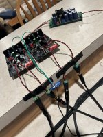
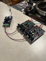
Quick question, I had made a BA3 based preamp in dual mono fashion but only one PSU is in use, there is some free space in the cabinet and since I have a turntable I was thinking at a phono stage to add to the preamp and somebody suggested the Pearl 3 to match, wondering if it would fit into the case and what is the power requirement, if I can use the Sigma22 PSU or just remove the unused one and try and fit the whole phono stage in the case.
Attaching a photo of the preamp
Grazie

Attaching a photo of the preamp
Grazie
@Giovanni1968, is the switching/volume solution you are using here available somewhere or was it custom?
Ciao @MattHauck it's an iSelect from Salas, you can find description here on the forum, relais switching input selector and place for the volume pot.
A big waste of space in the cabinet, I wish I can stuff a phono stage inside
A big waste of space in the cabinet, I wish I can stuff a phono stage inside
If your Sigma22 is +/-24V then it is a big jump down to the Pearl 3´s +/-15V. You either change transformer and mod the Sigma22 to output +/-18V, or take these out and reuse the space. Me, I would do the latter. If you do, you want to keep the Pearl 3 PCBs and PS as far appart as the enclosure allows. Perhaps stack the Pearl 3 PCBs if case height allows for it.Pearl 3 to match, wondering if it would fit into the case and what is the power requirement, if I can use the Sigma22 PSU or just remove the unused one and try and fit the whole phono stage in the case
Ciao @PierreQuiRoule my BA3 was arranged with +/-30V output as to have max gain to drive the F4 (this is another long story) so too much of a burden to redo it all just to use it, maybe it makes more sense to remove both the S22 and transformer and keep them for another project, at that point I will have quite some space inside the cabinet, I have to take the measures of the Pearl 3 boards and figure if they fit along with PSU and transformer
I think the kit comes with the PSU board too, I might just have the S22 and transformer removed and reutilise them to put together another BA3 in a simple fashion with a small cabinet, unfortunately the Pearl 3 kit is not available at this moment but I am just evaluating if it can make it as a good phono stage to couple to the BA3, I was thinking of the classic EAR834 but rather than another box I'd stuff it all into the existing one in the pursue of simplification
Ack. Maybe place the Pearl 3 PCBs in the bottom left corner. See if you gain any space by mounting the pre PCB vertically. Stack the remaining Sigma22 over the transformer in the top right corner. Place the Pearl 3 PS PCB transformer near the top edge, as far from the Pearl3 PCBs as practical.
If you have a computer, audio card and REW, then watch the PS noise in RTA mode as you move boards around in the case. This can give good insights.
If you have a computer, audio card and REW, then watch the PS noise in RTA mode as you move boards around in the case. This can give good insights.
The Pearl 15 volt regulators have a maximum input rating of 35 volts. The capacitors supplied around the regulators are rated at 50 volts and the heatsinks provided with the Pearl kit are more than adequate for 24 volt input. I'm using a supply of 27 volts and it works fine.
So the transformer should work just fine if there is enough space to stuff it all inside there, I will submit the project to the guy who assembled the preamp for me and hear his thoughts, he is very skilled and with plenty of testing equipment, he used to work on microwave TRX so plenty of experience and skills and, by the way, I am just looking at a suitable project to take form after October when my busy season will be over.
Edit:
if I remove the S22, move the transformers a hole or two to the front, both of them close, there sure is 100x100mm space to fit the PSU and the two other boards might just fit without to move other boards
Edit:
if I remove the S22, move the transformers a hole or two to the front, both of them close, there sure is 100x100mm space to fit the PSU and the two other boards might just fit without to move other boards
Last edited:
In the era of the ACA Mini and ACP+, how about an open air Pearl 3?
Actually, I just received these fully assembled boards (and nicely done) from @Dneu2011 and just didn’t have the patience to wait for the chassis.


Actually, I just received these fully assembled boards (and nicely done) from @Dneu2011 and just didn’t have the patience to wait for the chassis.


VRDN feeding the Pearl 3. That’s pretty cool.
Noise performance will be, of course, much better in a metal chassis. But I ran the prototypes open like that for a time and it still works surprisingly well.
Noise performance will be, of course, much better in a metal chassis. But I ran the prototypes open like that for a time and it still works surprisingly well.
Ive used a lot of these Iselect input switchers. Excellent stuff.Ciao @MattHauck it's an iSelect from Salas, you can find description here on the forum, relais switching input selector and place for the volume pot.
A big waste of space in the cabinet, I wish I can stuff a phono stage inside
Russellc
Getting ready to build my 3rd (and last) Pearl 3 for the home TTs. Have the chassis, the Dual PSU, and am waiting on the DIY package (thanks for the packing, Jim!). Have ordered a quality set of alternate R27 resistors ranging from 400-700 ohms (Vishay) and am ready to populate R27 with the right value as per Randy's instructions. But am not sure about certain possible R27 choices and, so, here are some questions for the knowledgeable gurus on this site.
1. Is it best to have both channels operating at the exact same current -- meaning insert some value in the left channel so that it measures, say, 4.9mA then adjust the right channel R value so that the same 4.9 mA is produced? Or is it better to use the same R value in R27 for both channels assuming both are under 5mA (say, left at 4.9mA and right at 4.8mA -- both with the same 500 resistor)? Both of my P3 builds so far have different mA values after using the same 680 resistors in R27 and they seem to operate fine (the difference for the second P3 between right channel 4.39 mA and left channel 4.16 mA is less than .3mA).
2. Is there a performance improvement by adjusting the current as close to 5mA as possible? The range between 3 and 5 mA seems large and I wonder what kind of audible change occurs with a low or high mA choice.
3. Is there somewhere else on the board to measure the results of R27 in order to create better balance/performance between the two boards?
I use only MC cartridges so the jiumper stays open with 70dB gain.
This is one fine piece of audio equipment and I look forward to completing my set so the vinyl needs of the next several years are in place. Now, if I could only get over the cost of Hana ML cartridges, my vinyl life would be ideal...
1) Current is all that matters, use whatever resistor to get current set.
2) Nope. Just get it in the ballpark.
3) No.
2) Nope. Just get it in the ballpark.
3) No.
After I received the assembled boards , I connected them to a lab supply for testing. I noticed there was a slightly higher current draw from the positive side…is this normal? They work just fine and sound great, I just wondered if there is any adjustment required, which I could do before putting them in a chassis.
Yes, the positive side pulls a little more, the first stage and CCS is referenced to ground, not V-.
- Home
- Amplifiers
- Pass Labs
- Pearl 3 Burning Amp 2023