Take a look at my build album for a possible method as wellJust so I'm clear: wrap a thin wire around a bolt from the CCS heat sink to G2 and solder to the board?
Attachments

Hi everyone, just wondering if anyone has a recommendation for a speaker protection board? I’ve seen that DIYAudio store has one, as does a couple of others including a sample project on pcbway. Are there any better ones that are available and recommended?
Check out the ones from XRK Audio on Etsy. They use solid state relays instead of the mechanical ones. Or ask XRK971 here on DIYA about them. I use them on all my big amps including the Wolverine.
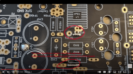
Hi, I have a question. I have the 4th GB EF3-4 boards. I have been studying @danieljw's excellent videos and @stuartmp's build guide. My board differs from the main boards shown there. They all have 3 vias to solder. I can only locate G1 via. The two missing ones are in the enclosed screenshot. It looks to me as if the via next to output coil L1 is replaced with a jumper, J104 (see photo). The via next to R127 seems to be missing altogether. I would be grateful for any help/clarification!
Attachments
Hi I'm mounting the boards in mirror configuration parallel to the heatsinks I have the trimpots R11, R25 with the side screw, I'm wrong if R25 doesn't care about orientation while R11 pin 1 must be as in the board? I already changed R109 with top screw to match pin 1 trimpot with pin on board.
Hi Guys,
I'm working on my Mouser order for Wolverine parts. The output transistors I selected are the Onsemi 2SC5200OTU and 2SA1943OTU. I need outputs capable of handling approximately 71 Volt rails. I'm also using a standard diyaudio 5U chassis. I noticed that these transistors will require drilling the heat sinks. I have a drill press and M3 drill and tap....so no problem. But I just want to know what I am getting into here. It's a standard TO-264 package. Will none of the 8 transistors on the EF3-4 pcb line up with the UMS holes in the heatsink? Or am I misunderstanding something?
Many thanks,
John
None of the 8 TO-264 transistors will line up with the "UMS holes". See the hole layout pdf in the group dropbox. Only EF3-3 with TO-3P outputs is "plug-n-play no drill/tap" on classis UMS layout. EF3-4 is longer than UMS anyway, so you would be drill/tapping on the outer edges just to mount the boards -some holes do match though. TO-264 parts are larger than TO3-P, therefore the mounting hole for them is further away from the boards by ~5mm.
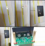
I have a 5u deluxe chassis arriving soon and have a completed EF3-4 board with TO-264 outputs, I can dummy it up and take a photo if you'd like.

As long as BOM part trimmers, will work either way around. Only difference would be winding direction changes. R11 and R109 has 2 pins shorted on the PCB where as R25 dont.
I have a 5u deluxe chassis arriving soon and have a completed EF3-4 board with TO-264 outputs, I can dummy it up and take a photo if you'd like.
I just finished my 4th GB boards and tested. I recall some Vias were removed so if you see them in the build guide but not on your boards you can just fill the ones you find and move on. For 4th GB boards you must install a wire jumper on J104 to ground the rail caps.Hi, I have a question. I have the 4th GB EF3-4 boards. I have been studying @danieljw's excellent videos and @stuartmp's build guide. My board differs from the main boards shown there. They all have 3 vias to solder. I can only locate G1 via. The two missing ones are in the enclosed screenshot. It looks to me as if the via next to output coil L1 is replaced with a jumper, J104 (see photo). The via next to R127 seems to be missing altogether. I would be grateful for any help/clarification!
Hi I'm mounting the boards in mirror configuration parallel to the heatsinks I have the trimpots R11, R25 with the side screw, I'm wrong if R25 doesn't care about orientation while R11 pin 1 must be as in the board? I already changed R109 with top screw to match pin 1 trimpot with pin on board.
As long as BOM part trimmers, will work either way around. Only difference would be winding direction changes. R11 and R109 has 2 pins shorted on the PCB where as R25 dont.
Hi Guys,
I'm working on my Mouser order for Wolverine parts. The output transistors I selected are the Onsemi 2SC5200OTU and 2SA1943OTU. I need outputs capable of handling approximately 71 Volt rails. I'm also using a standard diyaudio 5U chassis. I noticed that these transistors will require drilling the heat sinks. I have a drill press and M3 drill and tap....so no problem. But I just want to know what I am getting into here. It's a standard TO-264 package. Will none of the 8 transistors on the EF3-4 pcb line up with the UMS holes in the heatsink? Or am I misunderstanding something?
Many thanks,
John
I used TO264 Onsemi 2SC5200OTU and 2SA1943OTU in my EF3-3 and am content with there performance, they sound very clean. Also the thermal contact area of the TO264 housing is better then TO3p. However I used undrilled heat sinks, and drilled and tapped the needed holes myself. Keep in mind that the base plate of the Modushop heat sinks is 7 mm, you need a drill press with electronic depth gauge and special drill and tap for blind holes. I would not drill extra holes in an UMS heat sink, as the old holes will be underneath the package and have negative impact on the thermal transfer between the package and the heat sink.
mainframe99,
Thanks for the explanation; a photo would be much appreciated.
Johm
OmeEd,
I'm stuck with the 5U chassis. Could I fill the existing holes with solder or M3 screws to maintain thermal transfer? What would you suggest? And thank you for responding.
John
Thanks for the explanation; a photo would be much appreciated.
Johm
OmeEd,
I'm stuck with the 5U chassis. Could I fill the existing holes with solder or M3 screws to maintain thermal transfer? What would you suggest? And thank you for responding.
John
Turn each heatsink upside down and start from scratch with the holes.
Barely. It takes about 6mm2 off the total ~300mm2 contact area available. I wouldn't worry about that in this case.I used TO264 Onsemi 2SC5200OTU and 2SA1943OTU in my EF3-3 and am content with there performance, they sound very clean. Also the thermal contact area of the TO264 housing is better then TO3p. However I used undrilled heat sinks, and drilled and tapped the needed holes myself. Keep in mind that the base plate of the Modushop heat sinks is 7 mm, you need a drill press with electronic depth gauge and special drill and tap for blind holes. I would not drill extra holes in an UMS heat sink, as the old holes will be underneath the package and have negative impact on the thermal transfer between the package and the heat sink.
Not to scale - indicative only.
The FAR bigger risk IMO is someone getting the new hole too close to the existing hole, then your really up the creek. In that case do as RickRay suggests and start over.
Agreed with you on the depth thing however. You don't need an electronic depth gauge fancy press, watch Daniels build videos on how to set a drill press depth to an existing hole.
I'm rough, If the heatsink is too thin I just drill right through the heatsink or limit a standard drill press to ~10mm and tap as far as I can in the instances where a hole might clip a heatsink fin. Using black machine screws you can barely even see it from the outside. It doesn't compromise the heatsink or the fins. Does one sit there listening, looking at the side of your amp?
Last edited:
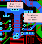
Hi, I have a question. I have the 4th GB EF3-4 boards. I have been studying @danieljw's excellent videos and @stuartmp's build guide. My board differs from the main boards shown there. They all have 3 vias to solder. I can only locate G1 via. The two missing ones are in the enclosed screenshot. It looks to me as if the via next to output coil L1 is replaced with a jumper, J104 (see photo). The via next to R127 seems to be missing altogether. I would be grateful for any help/clarification!
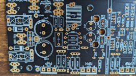
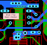
Don't worry, it's fine, top copper was added right through the center section under those resistors from V4.1 on-wards.
Adding the extra copper will help share the current between the top and bottom traces, but what is currently there is more than adequate, so don't worry.
Attachments
Trimpots are just variable resistors.R11 pin 1 must be as in the board?
They will still work no matter the orientation, however the direction that you turn the trimpot clockwise or anticlockwise to increase the resistance will change. The build guild will give you full details on what pins to measure depending on the orientation of the trimpot.
My advice is use a DMM and measure the resistance between pins 1 and 2 and then note the direction you need to turn the trimpot to increase the resistance before you install them.
Then check if the pin numbers on the trimpot match the pins numbers on the silkscreen of the boards. If they match then the direction you will need to turn the trimpot will remain the same. If the pin numbers are opposite then the direction that you'll turn the trimpot will be opposite to what you recorded above.
Good luck
OmeEd,
I'm stuck with the 5U chassis. Could I fill the existing holes with solder or M3 screws to maintain thermal transfer? What would you suggest? And thank you for responding.
John
Considering it's not possible to wind back history, and you already have TO3p drilled heat sinks, it makes sense to go on with TO3p packages. However not the Toshiba 2SC5200 and 2SA1943 as Toshiba has expressed concern on there use under heavy loads.
Alternative you can sell the UMS drilled heat sinks and order heat sinks without the drilling from modushop.biz
Finally, if you don't mind the aesthetic consequences, there is the by RickRay offered solution. Make sure upfront that none of the outputs will land on a predrilled hole as this will lead to uneven heating of the outputs
@mainframe99 This is not the way I do it, and I don't want my builds to be recognizable as DIY product on first sight. BTW, have you ever seen the el cheapo Chinese way? Drill a hole and slam a plate screw in it.
Hi guys,
Can I use RN55 Vishay Dale resistors instead of the CMF55 series where 1/4 watt is called for? I think the RN55s are rated .125 watt for the military, but are derated. I ask because I have boxes of 100, 1000 and 10k ohm RN55 resistors from prior projects.
Many thanks,
John
Can I use RN55 Vishay Dale resistors instead of the CMF55 series where 1/4 watt is called for? I think the RN55s are rated .125 watt for the military, but are derated. I ask because I have boxes of 100, 1000 and 10k ohm RN55 resistors from prior projects.
Many thanks,
John
I believe RN55 do shere CMF-data, other threads suggest the same. Degraded for military use.
I've only have RN55 and RN60 in my inventory, and never seen them fail or get hot when pushed to wattage ratings identical to the CMF.
I'm having the same doubts, should I buy CMF when I have lots of RN55???🙂
I've only have RN55 and RN60 in my inventory, and never seen them fail or get hot when pushed to wattage ratings identical to the CMF.
I'm having the same doubts, should I buy CMF when I have lots of RN55???🙂
- Home
- Amplifiers
- Solid State
- DIY Class A/B Amp The "Wolverine" build thread