Following up on this...If you're doing custom chassis and want to really minimize noise, consider monoblocks too.
My PSU will be dual-mono, but I planned on one large enclosure to contain both channels. Is there some noise benefit to having each channel in a separate enclosure?
Nothing that black sharpie can not fix. (Fully reversible if you do not like it).It is not the led. It is the silver colour and too big switch. And the position I don't like
One big advantage of monoblocks over dual mono would be being able to place the amps closer to the speakers and have shorter interconnects.Following up on this...
My PSU will be dual-mono, but I planned on one large enclosure to contain both channels. Is there some noise benefit to having each channel in a separate enclosure?
Less chance of interferance between channels due to physical distance.
Possibly some advantage in terms of grounding as each amp will have its own earth. Less chance of ground loops perhaps. (Thinking out loud).
I personally think the biggest advantage is aesthetic. Monoblocks look cooler. More high end. Look at the stuff that costs the real big bucks and the power amps are typically monoblocks.
Arguably harder to implement. The typically narrower chassis can may layout more difficult. More brackets required to fit things etc.
Less options for chassis. Modushop mono chassis, Ali express or fabricate yourself.
Higher cost. More metal, double the mains side wiring, power switches, fuses holders, iec recepitcals etc.
I think it is well worth the extra effort and expense but others may disagree.
Last edited:

Precautions to avoid ground loops are still necessary while using a dual mono setup. There is only one earth. The safety earth connections (connecting together in the house wiring), and the signal interconnects (connecting together in the pre-amp), can potential form a ground-loop.
Stuart,
First, thanks for everyone's contributions to the best build guide I've ever used.
Second, did I find something missing, or do I not see where it is? Shouldn't R15 be included on page 24?
Always happy to find a typo, or admit I missed it.
First, thanks for everyone's contributions to the best build guide I've ever used.
Second, did I find something missing, or do I not see where it is? Shouldn't R15 be included on page 24?
Always happy to find a typo, or admit I missed it.
Attachments

I'm busy testing my boards with a 30V bench PSU
D108 does not light, but the other LEDS do light. D10 and D11 do not light, but that's because of the low voltage
The voltage across R111A and R111b is just below 800mv
TP-105 to pos power rail is 1.2V
TP-105 to neg power rail is 1.2V
Outputs are 2Sc3503 2sa1381
I have checked the polarity of D108
D108 does not light, but the other LEDS do light. D10 and D11 do not light, but that's because of the low voltage
The voltage across R111A and R111b is just below 800mv
TP-105 to pos power rail is 1.2V
TP-105 to neg power rail is 1.2V
Outputs are 2Sc3503 2sa1381
I have checked the polarity of D108
Appreciating English may not be the first language.
"TP-105 to neg power rail is 1.2V" - This appears to be a typo or incorrect testing. The actual test is TP106 to negative rail. Please clarify.
Outputs are 2Sc3503 2sa1381 - This appears to be a typo or misunderstanding. "Outputs" are big 15A BJT's, you have reported transistors as outputs that are typically used for pre-drivers. Please clarify.
Do you have the output transistors installed? You shouldn't, if you are doing the initial 30V testing. You should only have pre-drivers and drivers installed and J103 installed just for this testing.
Please try to be more precise with your fault reports. Anyway;
First thing to check, are Q101 and Q102 installed correctly, I.E. facing opposite ways.
Try and provide quality photos of your work, most people here can spot faults fast. Most common install errors thus far have been transistors installed backwards or solder bridges accidentally shorting.
D108 lights up when tested in circuit with multimeter diode mode? possible bad LED?
Sorry, you're 100% right. Bad posting from my workbench.
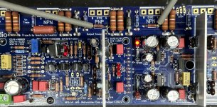
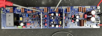
Testing my boards with a 30V bench PSU
D108 does not light, but the other LEDS do light. D10 and D11 do not light, but that's because of the low voltage
The voltage across R111A and R111b is just below 800mv
TP-105 to pos power rail is 1.2V (TP-105 (DMM -) and the positive power rail connection)
TP-106 to neg power rail is 1.2V (TP-106 (DMM +) and the negative probe on the negative rail)
Pre-drivers are 2Sc3503 2sa1381
I have checked the polarity of D108
Q103 is currently mounted above the board. I had it mounted under the board, but had reversed it accidentally. So I desoldered it and temporarily mounted to the top
Q107 (MJE15032) and Q108 (MJE15033) are currently mounted under the board.
Pics attached.
First thing to check, are Q101 and Q102 installed correctly, I.E. facing opposite ways.
Yes, checked those, they are.
D108 lights up when tested in circuit with multimeter diode mode? possible bad LED?
I actually replaced it on one board. and I have tested a few times.
This is happening on both boards. So I don't think it is a bad solder joint or a solder bridge
Attachments

Last edited:
D108 is just there to indicate negative rail voltage is present on the IPS.
Wrong value resistor for Rled2?
Else measure if there is actually the right voltage between TP106 and G2
Wrong value resistor for Rled2?
Else measure if there is actually the right voltage between TP106 and G2
Last edited:
Check the LED lights in circuit
Measure RLED 1 and 2 from the back of the PCB to confirm both making contact and are same value.
Check voltage at TP106 to GND is roughly test voltage
I think (possibly, photo a bit grainy) you have no rail voltage at TP106 because Q101 and Q102 appear to be from a different family? Are Q101 and Q104 mixed up? Wrong transistor / pinout?
Question re Wima film cap 100 pF at position C0 on the Input Board
This cap is rated for 1kV. I have 100 pF Wima film cap rated for 400 VDC. Can I use the lower voltage rated cap at this position or will it routinely see greater than 400 VDC?
Many thanks,
John
This cap is rated for 1kV. I have 100 pF Wima film cap rated for 400 VDC. Can I use the lower voltage rated cap at this position or will it routinely see greater than 400 VDC?
Many thanks,
John
Check the LED lights in circuit
They're definitely in circuit
Measure RLED 1 and 2 from the back of the PCB to confirm both making contact and are same value.
I checked them and swapped them out just in case.
Check voltage at TP106 to GND is roughly test voltage
This is where the issue is TP106 is about half the voltage of TP105
I think (possibly, photo a bit grainy) you have no rail voltage at TP106 because Q101 and Q102 appear to be from a different family? Are Q101 and Q104 mixed up? Wrong transistor / pinout?
Different packages, I thought being non-critical this would be okay, but I switched them out for the same package
- Home
- Amplifiers
- Solid State
- DIY Class A/B Amp The "Wolverine" build thread