
My Wolverine has 2SC5359/2SA1987 on outputs....TOSHIIIIIBAAA!!
How do these compare to the Onsemi devices, 4281/4302?
Dan
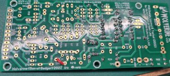
I'm using 2sa1930/sc5171 as drivers in Honey Badger (+/-63V) and a couple of other amps without any problems.View attachment 1331231
(ignore 2SC5359/2SA1987 are an output BJT)
Hi everyone, just wanted to drop in, introduce myself and say thanks for the amazing info throughout this thread. It’s impressive how much time and effort has been put into this design by everyone here.
I’ll be joining in and building up a pair of EF3-4 boards from the 3rd group buy. At the moment, I’m just reading, learning and gathering components. Hopefully I can contribute something useful to the thread in the future!
I’ll be joining in and building up a pair of EF3-4 boards from the 3rd group buy. At the moment, I’m just reading, learning and gathering components. Hopefully I can contribute something useful to the thread in the future!
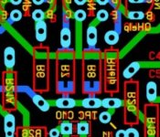
Looks Like R7 & R8 on the input board are set up for SMD or resistors. Reviewing photos of past builds, I don't see any that chose to use SMD. Is there a reason for that? The SMD parts offer 0.1% tolerance vs. 1% for the resistors. Does that not make a difference for these parts?
You can use either, I found though there is more selection of 0.1% resistors in TH vs MELF. Or you can by extra 1% and match them.
I should add that R7 R8 are MELF 0207 and mouser only list 1% tol for those parts.
I should add that R7 R8 are MELF 0207 and mouser only list 1% tol for those parts.
Last edited:
I was looking at: https://www.mouser.com/ProductDetail/279-SMAA0204BTNX220R?You can use either, I found though there is more selection of 0.1% resistors in TH vs MELF. Or you can by extra 1% and match them.
I should add that R7 R8 are MELF 0207 and mouser only list 1% tol for those parts.

Thanks wolverine team. I love it.
And yes, it is heating a lot. Also the class A was... waiting for winter. Now we have 39°C outside.
But they do fit my 2022 boards. I can see the evolving boards will be a bit confusing.yes thats 0204 not 0207, 0204 wont fit latest version of the PCB those pads were changed.
Look at the bottom of the BOM you will see the REV changes, not sure why the SMD size didnt get changed though on the IPS
2nd GB May 2024 for your boards Chiptech. Has some updated bias notes.
Andy right, the MELF part listed on the 4th GB BOMs is currently a bit small.
There's also an ancient error on the 1st GB BOM that's probably not going to affect anyone, but the 1% Mica part listed for C5 for MJE drivers is the larger CD19 series which has larger lead spacing. The correct fitting part is CD15FD471FO3F
Thanks for the heads up on that. I'll look into it. I did recently see there was a discrepancy between the bom and the pcb. I have been talking with Harry to look into it. I had a quick look at the pcb and don't see any reason why a small footprint can be used or why it was changed. Maybe the one from R3,4 was copied into the position of R7, 8.yes thats 0204 not 0207, 0204 wont fit latest version of the PCB those pads were changed.
Attachments
You can always put a resistor in series with the power for the led to dim it a little.But I don't like the switch on front panel.
- Home
- Amplifiers
- Solid State
- DIY Class A/B Amp The "Wolverine" build thread