ah ok, it is there now. Sounds a bit as "grid leak bias" https://www.diyaudio.com/community/threads/grid-leak-bias-how-does-it-work.272689/ but probably not the case. If you have the chance please post another picture of the current build, as globulator said it is a simple circuit and we debug it 🙂
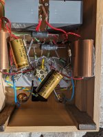
It's a mess now with all the changes done.. 🙁
220k feedback has been removed...just so you know,
220k feedback has been removed...just so you know,
Attachments

b+ -> 1k -> pin 9 (G2)
Something like a few volts lower than b+...don't remember the exact voltage.
Something like a few volts lower than b+...don't remember the exact voltage.
As you have dc volts on el84 grid then C1 is not doing its job of blocking dc current while passing only the signal ac current.
It appears to be leaky and needs replacing.
Any value over 220nF will do just for testing.
It appears to be leaky and needs replacing.
Any value over 220nF will do just for testing.

Hello Bas,
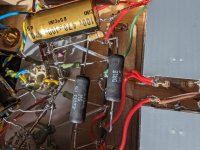
I have used these wirewound Dale resistors too in the past. The connecting wires are steel and should be cleaned/ scotchbrited to assure sufficient soldering properties.
There is no short somewhere with all those bare wires? Sometimes it takes just an accidental move of one part to create a non working device.
Of course like someone wrote sometime ago. Pulling tubes, discharge caps and check every possible connection on paper with the actual situation.
Greetings Eduard
I thought the same, a leaky coupling capacitor, but generally they cause a positive voltage on G1 that causes a runaway, in this case the voltage at G1 is negative. But taking out the cap for the moment, and remeasuring all voltages is a good idea nevertheless.
But I very much agree with globulator: unpower, take out the tubes, and measure conductivity/resistance from each pin to its surroundings.
But I very much agree with globulator: unpower, take out the tubes, and measure conductivity/resistance from each pin to its surroundings.
Must be it. Thought of that as well...but thought I may have bought them new..could have bought them 2nd had...I've forgotten. Will check this evening!As you have dc volts on el84 grid then C1 is not doing its job of blocking dc current while passing only the signal ac current.
It appears to be leaky and needs replacing.
I also do that.The connecting wires are steel and should be cleaned/ scotchbrited to assure sufficient soldering properties.
Hello Bas,
They have the looks of the typical audiophile cap.
If they are 400 volt dc and you fire up a choke input with 350-0-350 volt ac (but higher with no current running!) with no minimum current resistor installed it will behave like a cap input and you will have around 500 volt dc at the first cap. Don't know how much of it will also pop up at the coupling cap?
What i do know that most caps designed for audiophiles can't stand any abuse
Greetings Eduard
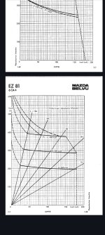
P.s the attachment will also show the effect when the choke is not big enough. The more H you have the less current you need to waste through the minimum current resistor.
Happily your choke has plenty of H
If i am right sometimes cap become leaky after a certain treshold. You could temporarily replace them with a professional cap. Just one channel just for testing
They have the looks of the typical audiophile cap.
If they are 400 volt dc and you fire up a choke input with 350-0-350 volt ac (but higher with no current running!) with no minimum current resistor installed it will behave like a cap input and you will have around 500 volt dc at the first cap. Don't know how much of it will also pop up at the coupling cap?
What i do know that most caps designed for audiophiles can't stand any abuse
Greetings Eduard
P.s the attachment will also show the effect when the choke is not big enough. The more H you have the less current you need to waste through the minimum current resistor.
Happily your choke has plenty of H
If i am right sometimes cap become leaky after a certain treshold. You could temporarily replace them with a professional cap. Just one channel just for testing
Attachments
I'd be suprised and angry if they were faulty. They have become so expensive I would never buy them now.
"Or bring up the voltage with no output valves and check the grid voltage to make sure the coupling caps are ok."
0V"Or bring up the voltage with no output valves and check the grid voltage to make sure the coupling caps are ok."
Perfect! 6,5v on one side 7v on the other so ballbark 43mA and 47mA!And now the output stage without the 6n3
I don't understand what is wrong though.....
Last edited:
What are the voltages at the plate of the 6N3 and the EL84?
I would desolder one side of the coupling cap, maybe the side at the plate of the 6N3, and see what it does.
All looks well, I am running out of ideas, and then one just tries around.
If nobody said it yet, very very strange 🙂
I would desolder one side of the coupling cap, maybe the side at the plate of the 6N3, and see what it does.
All looks well, I am running out of ideas, and then one just tries around.
If nobody said it yet, very very strange 🙂
- Home
- Amplifiers
- Tubes / Valves
- Another SE EL84. Following this schematic. Grid stoppers yay or nay?