Thans Eduard,
I did the transformer swap last night. I first measured the other transformer to see if it was not perhaps mislabeled. Turns out the label was correct.

I did the transformer swap last night. I first measured the other transformer to see if it was not perhaps mislabeled. Turns out the label was correct.
Last edited:
Old:

New:

After this picture I added to 33k/10Watt resistors in parallel after the choke to always draw some current as Eduard suggested. And as is customary.
New:
After this picture I added to 33k/10Watt resistors in parallel after the choke to always draw some current as Eduard suggested. And as is customary.
Last edited:
Long story short. The noise was not from this amp. But the bypass cap just made the preamp noise more audible. So I swopped the 21st century maida from my own version to the store bought version (Waaay too expensive...especially after customs and admin costs) Noise came down. But still some noise.
Anyway. The noise levels are fine for the time being..100db sensitivity speakers.
But here is the next issue. For some reason each el84 draws only around 20mA. I just ripped the 6P14p-ev out the box...so I'll try some others. The Russian EL84's are from the mid 80's which apparently was not a good vintage.
I'll keep you all posted...but if you have suggestions in the mean time..go ahead.
Hello ,
Resistor should be close to 13,50kohm to draw sufficient current,!!
And have high enough voltage rating.
greetings, Eduard
P.s need to eat here in Vietnam
Resistor should be close to 13,50kohm to draw sufficient current,!!
And have high enough voltage rating.
greetings, Eduard
P.s need to eat here in Vietnam
Hello Bas,
With choke input there is no need to use the resistors in series with the high voltage winding because as you can read in the link the choke limits the current to a steady value.
The bleeder circuit looks low power rating. It is not there to draw some current .It is there to draw a minimum amount of current ALL the time.You must check the voltage rating of the resistors especially the young if you use 3 in parallel.
Now you have a true choke input? How much dc voltage on the first cap after the choke. The bleeder should be across that cap. If it isn't there and your circuit is not drawing current your high voltage will go up seriously like there is no choke at all.
Once you have the desired voltage on the first cap you can start fiddling around with the second RC network.
You can of course change the output tube from left to right and see if the low current moves to the other channel.
Could be a bad solder joint?
Greetings Eduard
P.s you speak Vietnamese so difficult
.
I just googled the Vietnamese word. But I do have a Vietnames friend. It indeed sounds like a tough language to pronounce and learn.
The resistors have a 700VDC voltage rating. And are ofcourse across the first cap after the choke. Voltage is around 300VDC. And goes up slowly and surely.
Both tubes draw too little current.
The resistors have a 700VDC voltage rating. And are ofcourse across the first cap after the choke. Voltage is around 300VDC. And goes up slowly and surely.
Both tubes draw too little current.
Hello Bas,
So voltage is ok, it won't change much if you draw extra current because it is choke input.
I would leave out the solid state diodes.
So the current is to low but is the sound any better or you need to replace the output tubes?
Are the heater voltages ok?
Strange that both tubes draw not the current they need to do.
But a good thing you have a choke input without an investment. Maybe there are some things that could be changed to fine tune the power supply.
I like the first cap to be a paper in oil or a Siemens mkv which is some kind of plastic in oil.
Greetings Eduard
PSUD concurs.With choke input there is no need to use the resistors in series with the high voltage winding because as you can read in the link the choke limits the current to a steady value.
Hello Bas,
These resistors are only mentioned in the capacitor input part of the datasheet.
But with the choke there is always a minimum number of H indicated for the choke.
All this has been like this for decades and will not change in the future.
Of course this knowledge is a bit fading . There are even people who say that caps can have such high capacity numbers today that we don't need chokes anymore.
I hope you will get the tubes drawing the right correct so you can give us your judgement upon choke input. Of course if the current is to low because of something that will also effect sound we should wait .
Greetings Eduard
Put in tubes that I know are good. One draws 11mA and the other 12mA.
Measured the grid -20vdc.
What I did:
I lowered grid leak from 680k to 470k. No difference.
Snipped out the 220k feedback resistor. No difference.
Next up. Lower the EL84 resistor to 130.
Really flabbergasted by this. Checked...and double checked. If it was a bad solder or socket...you would not expect them to be the same on both channels.
Perhaps rebuild it.
Hello,
Could it not be the input tube?
Maybe check the battery on your multimeter.
It would be really weird if you have to use completely different resistor values than usual to get correct results with tubes that you know are good.
Sometimes there could be the same mistake in both channels , maybe the resistors are far off from indicated value?
You need someone more experienced to share his ideas.
Greetings Eduard
Hello Bas,
Lowering the cathode resistor will make the current go up through the EL84 but i think you should be able to get it right with the usual values unless your circuit is completely different of course.
The cathode resistors still have their indicated value. They have never been overheated? Maybe just replace one with a brand new one and check the current right after switching on. Sometimes the end cap on the resistor not making a proper contact can do strange things.
Hope for the experts to react soon . High voltages and heaters are ok?
Greetings Eduard
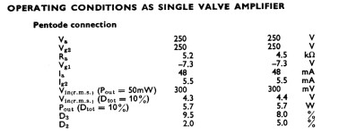
How strange your readings compared to #78....which were close to the mullard pdf values.
Hope output transformer DCR values haven't deviated from the as new value.
What is O/pt transformer DCR bas?
"Measured the grid -20vdc."
Do you mean cathode voltage?
Hope output transformer DCR values haven't deviated from the as new value.
What is O/pt transformer DCR bas?
"Measured the grid -20vdc."
Do you mean cathode voltage?
Attachments
Last edited:
Indeed.How strange your readings compared to #78.
Post 78# = 30mA on one el84. 36mA.
I've also seen 20mA/25ma or similar...but now consistently low.
Could it not be the input tube?
Looks good 5mA each half.
I'll check batteries.Maybe check the battery on your multimeter.
Come to think of it. The last couple of times I measured withoud load resistors in te secondaries of the ot. And no input (Usually a google audio cast)
Because of lazyness.
Because of lazyness.
Hello Bas,
I always " learned" that you should always have a load resistor on the secundairy of the output transformer. If i remember correctly you should make it high enough so it won't steal any of the power meant to be give to your loudspeakers.
Or you could use a high power lower ohm resistor that you will connect all the time when your speakers are disconnected.
I think the current going through the power tube should be in the same ballpark if everything is working as it should.
Absolutely not sure but i think even if you would pull the input tube the current in the output tube remains the same.
Maybe copy and paste the circuit and open a new ( temporary?) thread so new people will take a look.
What is the difference with the circuit where you had the right currents running?
Are you sure the heater supplies are okay?
Greetings,Eduard
Never checked the heater supply. Will do.
I normally use a 18R resistor because I had them lying about in 7 watt version. I always use them. Except the last couple of times.
I normally use a 18R resistor because I had them lying about in 7 watt version. I always use them. Except the last couple of times.
Don't know really.What is the difference with the circuit where you had the right currents running?
- Home
- Amplifiers
- Tubes / Valves
- Another SE EL84. Following this schematic. Grid stoppers yay or nay?