Hello,
Indeed cap input and choke input are different topologies. But with the circuit Bas is using both should work properly.
But as long as there are no drastic changes in the circuit both will keep working. However choke input is a different animal so to say when executed properly it will give your amp a more powerful presence.
I am no expert on cars but it is a bit like 4 and 8 cylinders even at normal speed the 8 cylinders will do things are greater ease. But Bas will tell us once the error has been found.
Greetings,Eduard

Without coupling capacitors both driver and power tubes bias correctly.
Driver tubes 4.1mA per side (2.3v over 560R)
Power tubes 42mA per tube
Remove one coupling cap. That power tube bias goes south.
6,3v ct to ground instead of raised voltage node does not change anything.
Driver tubes 4.1mA per side (2.3v over 560R)
Power tubes 42mA per tube
Remove one coupling cap. That power tube bias goes south.
6,3v ct to ground instead of raised voltage node does not change anything.
Apologies, what does this mean?Remove one coupling cap. That power tube bias goes south.
All good until you add a coupling capacitor?
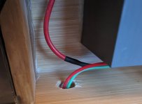
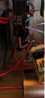
Are the sub chassis tied to earth.....I can't see from the images provided.If so do you
May be add decoupling cap to 6n3 R7.
BTW Bas how do u mate PS to amplifier......I can't see it.
May be add decoupling cap to 6n3 R7.
BTW Bas how do u mate PS to amplifier......I can't see it.
Last edited:
Hello,Apologies, what does this mean?
All good until you add a coupling capacitor?
VeRy probably.
Maybe the coupling capacitor should be mounted with more isolation towards the chassis.
Maybe it is connect to the wrong "terminal"?
Maybe someone with some " drawing skills" should make a simple drawing and ask other folks why removing this cap is getting the currents correct?
Greetings Eduard
Something is very much not as we all think it is. Where did a negative voltage come from? Maybe a wider picture would help.
All good fortune,
Chris
All good fortune,
Chris
I wasn’t suggesting to do it here. Just thinking loud.Thanks @zintolo I was not thinking about such a big change (unset, Fets)
Yes.Apologies, what does this mean?
All good until you add a coupling capacitor?
BTW Bas how do u mate PS to amplifier......I can't see it.
Attachments
Looking back at the schematic, most times there is a RC filter between the B+ for the output stage and the driver stage, decoupling the power to the driver from the output stage. Without the caps we have a common B+ for independent stages, so individually they work nice. But as soon they are coupled with the cap, some oscillation may arise, thinking specifically about motorboating that happens due to insufficient decoupling of the individual stages (struggled with that in one of my current builds...)
If I understood well, before changing to choke input supply, the amp was working but presenting too much noise?
I would try something as the RH84, where the driver is decoupled with an additional RC consisting of a 10k and 100uF, or some values in that region (100uF could probably be much less...) https://rh-amps.blogspot.com/2013/02/rh84-amplifier-revision-2_26.html
Bas, if you had a scope you would already have used it?
The negative voltage at G1 is indeed weird, if it was really -20V + the cathode resistor in place, the tube would maybe indeed pass 10mA, but I think that it may be oscillating and that is throwing the reading from the DVM off.
The presence of a negative voltage, referenced to chassis, means that the umbilical from the power supply chassis is not connected to amplifier chassis - right? Where else could a negative voltage come from? Yes, maybe oscillation, but why the interaction with coupling cap? Still, a good avenue to explore.
On second thought, yours is a perfect explanation. Maybe test by removing feedback, move FB resistor to feed from B+.
All good fortune,
Chris
On second thought, yours is a perfect explanation. Maybe test by removing feedback, move FB resistor to feed from B+.
All good fortune,
Chris
I found something. And I'm sure it is the issue that is causing the problem. But I don't know how and where it comes from.
When the amp is off. There is no continuity between signal ground and the chassis where the tubesockets are in. So the chassis is not connected to ground. (I have grounded the psu part to the chassis though.)
Turn the amp on. Continuity when the b+ comes up...not a solid beep...but like a diode switching.
AC 22 volt potential between that chassis and signal ground when power is on. Obviously none when switched off.
Do not know how that potential gets to any other part of the chassis and into the circuit.
I gave away my scope because I did not know how to use it.Bas, if you had a scope you would already have used it?
So, you had measured the negative voltages by referencing the chassis? But the signal "ground" wasn't connected to chassis? If so, an easy fix - connect them.
All good fortune,
Chris
All good fortune,
Chris
Both continuity testers and AC voltmeters are easily fooled in this circumstance, and in turn will fool us. It seems like a simple task, and usually is, but in this case can lie like a rug.
Always the best,
Chris
Always the best,
Chris
Solved. What remains for me is why a voltage develops between signal ground and my chassis? And how that got somehow into my circuit? Leaky tube socket?If so, an easy fix - connect them.
"May be add decoupling cap to 6n3 R7."
Should read "Maybe add bypass cap to 6n3 resistor R7."
"Are the sub chassis tied to earth.....I can't see from the images provided.If not please do so"
" So the chassis is not connected to ground. (I have grounded the psu part to the chassis though.)"
👍
Should read "Maybe add bypass cap to 6n3 resistor R7."
"Are the sub chassis tied to earth.....I can't see from the images provided.If not please do so"
" So the chassis is not connected to ground. (I have grounded the psu part to the chassis though.)"
👍
Well that is why I started checking continuity. So it was a vital clue."Are the sub chassis tied to earth.....I can't see from the images provided.If so do you"
Usually all my chassis are floating.
Probably indeed a capacitive connection, the DVM has a very high input capacitance, so can barely discharge this potential.Solved. What remains for me is why a voltage develops between signal ground and my chassis? And how that got somehow into my circuit? Leaky tube socket?
- Home
- Amplifiers
- Tubes / Valves
- Another SE EL84. Following this schematic. Grid stoppers yay or nay?