
Hello,
An oscillation in the input stage can cause this much reduction of current in the output tube?
Swap the cap is the next step i guess or first check every connection without tubes and compare it to circuit on paper.
Greetings, Eduard
An oscillation in the input stage can cause this much reduction of current in the output tube?
Swap the cap is the next step i guess or first check every connection without tubes and compare it to circuit on paper.
Greetings, Eduard
Replaced the caps with new Cornell Dubilier 1200v 0,1uF caps. Same problem.Time for what I said in #165.
In a way I'm relieved it's not the coupling caps. That would have been 50 euro down the tube and good caps as well.
Would have been good to solve the problem......anyway thanks Bas you have expanded my knowledge and understanding.One for the memory banks.
"50 euro"😵
"50 euro"😵
Last edited:
Yeah. They are 124 euro now. 62 a piece. I bought them 6 years ago. 25 was bargain looking back.
I'll try that. The grounding thing.
I'll try that. The grounding thing.
A question for
"Say the ripple at the B+ goes up (shown by the arrow up). This ripple will be present at the plate of the tube (impedance of the transformer is much higher than the plate impedance). The ripple will be passed (attenuated) to the cathode of the driver tube. Given there is no ripple at the grid of the driver tube, the ripple at the plate of the driver tube will be inverted, and passed to the grid of the output tube. The cathode of the output tube gets the ripple from B, so the cathode and grid of the output tube have ripple in opposing phases, which then gets amplified (and not cancelled, what I hoped for)."
Looking at my #100
The output stage is dc biased.....no ripple appears at the cathode as it is tied to ground.
Therefor very little noise appears on the output.....
Is that so?
ErikdeBest
from your analysis...."Say the ripple at the B+ goes up (shown by the arrow up). This ripple will be present at the plate of the tube (impedance of the transformer is much higher than the plate impedance). The ripple will be passed (attenuated) to the cathode of the driver tube. Given there is no ripple at the grid of the driver tube, the ripple at the plate of the driver tube will be inverted, and passed to the grid of the output tube. The cathode of the output tube gets the ripple from B, so the cathode and grid of the output tube have ripple in opposing phases, which then gets amplified (and not cancelled, what I hoped for)."
Looking at my #100
The output stage is dc biased.....no ripple appears at the cathode as it is tied to ground.
Therefor very little noise appears on the output.....
Is that so?
Hi pl802.
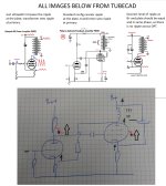
For the schematic in post #100 I think that the Tubecad analysis (middle figure on the image, also 2nd picture in post 91 https://www.diyaudio.com/community/...toppers-yay-or-nay.407491/page-5#post-7571412) does apply, because in both cases (with fixed bias) and in tubecads analysis, the ripple at the cathode is 0V.
I actually reconsidered my analysis this morning, and now I don't know the impact of ultrapath in the PSRR of this amplifier. Broskie shows that the Ultrapath has worse PSRR in SE case https://www.tubecad.com/2008/08/blog0147.htm (I copied the relevant picture into my analysis). What I did wrong in my first analysis is that I reversed the phase of the ripple at the plate of the input tube, but a cathode coupled design does not invert phase, so the phase at the plate is the same as at the cathode. This is transmitted to the grid of the output tube, the grid and cathode have the same phase, so the grid helps to attenuate the ripple at the plate, so it will not be as bad as in the ultrapath SE power amplifier anymore. But does it attenuate all, so that the plate has no ripple, as in the middle figure? Not good either. Good would be if it attenuates just enough that the ripple at the B+ and at the plate are the same level and phase, now the OPT has zero netto ripple at it's primary and so no ripple at the secondary.
This would be an excellent case for a simulation, hint at @zintolo and @euro21 🙂
But it does nothing on solving the problems experienced by Bas at this moment.
Attachments
Hi Bas,So I'll take it apart and rebuild it. And analyse the old circuit...probably this weekend.
before disassembling everything, would you take out only the coupling caps, plug in all tubes and see if the individual stages bias up well? I mean, about 40mA through the EL84 and 4 to 5mA through the driver tubes?
Good luck!
Erik
Hello,
That is an excellent idea!!
If it will show they both work well independantly it will give us ( i mean the professionals)more info about what could be wrong.
But we might need someone who did not visit this thread who possibly can tell us right away what is wrong. I already suggested to Bas to open a new thread.
Greetings Eduard
Thanks, I will try that. It's even easier and cheaper to inject it having high-impedance cathode-driven pentodes à la UNSET.This would be an excellent case for a simulation, hint at @zintolo and @euro21 🙂
Hello,
I think we should focus first on getting Bas device in working order.
In the last decades we have seen some revolutionary new topologies pop up. Some people will give it a try and will say triple WOW and one year later they will be back at the original circuit because they felt something was missing.
Most " new things " have been explored by the good old engineers from the past.
Most things presented as something new did end up in a drawer for a reason.
Sometimes they can turn out to be interesting now because new technology allows us to create a better cap or anode choke. But many times the companies nowadays are looking for profit margin not improvement.
I always tell people when i was young you could buy a washing machine that would last two decades and could be repaired to add one more decade. Now it will last a few years and will be hard to repair and it would be cheaper to get a new one.
Greetings Eduard
Hello,
Better get it working as intended first before changing its topology.
After that you could maybe use some other resistors.
I would replace the first cap after the Lundahl choke by something like a Russian k75-10. Put it really close to the lundahl terminal and have its other " end " connected to the 0 by the shortest wire possible.
The lundahl is said to make the life of the caps a lot easier but still i heard from several people the first cap should be an "oil type "
Greetings,Eduard
Hi Eduard,
Indeed, the ultrapath was full hype, until weaknesses were shown, and I haven't seen in much anymore. I am just thinking that in this case it could help, let's see if Zintolo's simulations work. In the end it is only changing the position of a cap - I admit, voltage rating must be changed as well, as in ultrapath it is between B+ and cathode (almost gnd), so needs to be a HV cap. I think that changing the power supply from cap input to L input is a bigger change of topology, luckily Bas has a choke that is up to the task.
best regards,
Erik
Thanks @zintolo I was not thinking about such a big change (unset, Fets), more how ripple behaves in this simple circuit. I remember some suggestions by Broskie where he does an ultrapath kind connection, but with two caps as a voltage divider, so only part of the ripple gets injected to cancel out other ripple, well, his Aikido sort of work.Thanks, I will try that. It's even easier and cheaper to inject it having high-impedance cathode-driven pentodes à la UNSET.
- Home
- Amplifiers
- Tubes / Valves
- Another SE EL84. Following this schematic. Grid stoppers yay or nay?