I'm trying to understand how the copper shield reduced the harmonics if the problem was from the rectifier.The principal harmonics are even, meaning they originate from the rectifier rather than the transformer. A parasitic DC component of the mains might have the same effect, but I am not sure about that; may need to do some physical tests
I’d argue that mechanical vibration and stray magnetic fields are two separate issues. Although one might have both.
You can take a as big of a piece of 18ga mild steel as will fit in available space, and interpose it between the transformer and the mono block. If you move the piece of steel around do you hear any difference? See any difference in an FFT of your system?
Rectifiers can make the transformer ring?I'm trying to understand how the copper shield reduced the harmonics if the problem was from the rectifier.
The rectifier hypothesis also doesn't explain the substantial reduction of 50Hz spike amplitude I observed at the amp's output.I'm trying to understand how the copper shield reduced the harmonics if the problem was from the rectifier.
No, I'm not suggesting that - the harmonics I was referring to were wrt the mains noise. I am trying to understand how a thin copper shield could reduce 50Hz noise as Salas described and how it reduces the even order harmonics. I can only postulate that the 50 Hz spike reduction is a result of the copper shield intercepting the stray mag flux due to leakage flux where the copper is acting as a shorted turn.Rectifiers can make the transformer ring?
I'll have to digest this https://research.engineering.nyu.edu/power/sites/engineering.nyu.edu.power/files/uploads/leakage 2.pdf
The 150 and other 50 ~Hz harmonics I'm guessing are radiated stuff from the wiring etc as a result of the rectification process.
Summarised nicely in post #47
https://www.diyaudio.com/community/...-how-to-defeat-hum-pickup.405352/post-7509263
Last edited:

Think I suggested the basic idea of a shorting turn interacting with leakage flux back in #43, #47, and #68. Maybe you'll have more luck than me convincing folks.
I used to see snubbers on the 4 diodes of bridge rectifiers but these seem to have been superceded by snubbers on the transformer secondaries (a la Quasimodo).
Does snubbing in either (both) location(s) mitigate the effects we're discussing? Could they?
Does snubbing in either (both) location(s) mitigate the effects we're discussing? Could they?
Tomorrow, I'll try to test the DC component hypothesis to explain the generation of even-order harmonics
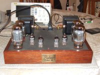
Yet another example... Once I put together this tube amp of my own design. A push pull KT-88 in triode mode it was. Free flow wired in spaghetti style. The chassis and Audio Note output transformers were provided from a Korato KVA-20 amp I gutted. The chassis was small. The 250VA mains toroid smack in the middle induced audible hum to it of course. After a circumferential copper wrap it did not have easily audible hum. For those ground return lines I couldn't avoid to come almost in touch with it I used one way grounded shielded coax. That brought the last touch on silence. I was chuffed to see its FFT so nice for harmonic noise. Tube amps generally suffer there. I listened to it for years. Very nice musicality. It ended up with a guy eventually using it on sensitive Altec A5 Voice Of The Theater horn speakers. Cause it was the most silent tube amp he ever tried on them he said.
Attachments

The thin copper band vs thicker band main difference is its more warming up due to Eddy me thinks. They both caught the hum field radiation sufficiently.Think I suggested the basic idea of a shorting turn interacting with leakage flux back in #43, #47, and #68. Maybe you'll have more luck than me convincing folks.
Looks like there are two radiating sources to consider in a toroid
1. Leakage flux. Very low in a toroid, but still a factor. Looks like this flux is trapped by the copper electrostatic shield, but I haven't worked out the exact mechanism.
2. 'circumferential' fields arising on the outside of the windings. This happens because the mag field around each wire on the outer side of the transformer has a small amount of the field that does not return couple through the core, but instead links up with the windings next to it so you have a circular field that kind of 'floats' around the outside windings. This is the main radiating mechanism in a toroid. When you wrap a GOSS band around it, it causes a current to flow in the GOSS band that generates a field that is opposite to the circumferential field and the two cancel quite effectively.
I see Salas used thick copper sheet, and given (2) above, that would account for the noise reduction. GOSS is used more regularly because it is cheaper I image.
I'll do some more digging.
That is an impressive FFT Salas. 👍Yet another example... Once I put together this tube amp of my own design. A push pull KT-88 in triode mode it was. Free flow wired in spaghetti style. The chassis and Audio Note output transformers were provided from a Korato KVA-20 amp I gutted. The chassis was small. The 250VA mains toroid smack in the middle induced audible hum to it of course. After a circumferential copper wrap it did not have easily audible hum. For those ground return lines I couldn't avoid to come almost in touch with it I used one way grounded shielded coax. That brought the last touch on silence. I was chuffed to see its FFT so nice for harmonic noise. Tube amps generally suffer there. I listened to it for years. Very nice musicality. It ended up with a guy eventually using it on sensitive Altec A5 Voice Of The Theater horn speakers. Cause it was the most silent tube amp he ever tried on them he said.
I guess if DC is present it will shift the hysteresis curve one way or the other depending upon the offset polarity - ie core magnetization is then not symmetrical, so you would get even order harmonics as a result. Be interesting to see what you find.Tomorrow, I'll try to test the DC component hypothesis to explain the generation of even-order harmonics
All tubes AC heated forgot to mention 😉That is an impressive FFT Salas. 👍
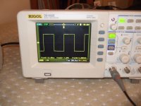
I have tested the DC hypothesis.
This is the test setup:

The transformer is a 40V/80VA, with a suitable dummy load.
The input is connected to the mains via back-to-back diodes, with the option of adding one more in series for one polarity:

In the vicinity, I placed the inductive probe of the humboy with its line out connected to an oscilloscope.
I used the FFT function of the scope to visualize the harmonics. The function is relatively crude, but perfectly sufficient.
This is the spectrum when the extra diode is shorted:

The 100Hz amplitude is negligible, practically at the noise floor.
Now, here is the situation with the shorting link removed:

The amplitude jumps to -14.3dB: QED, DC bias affects the generation of even harmonics.
Interestingly, a magnet placed against the magnetic circuit has a similar effect, just much less pronounced
This is the test setup:
The transformer is a 40V/80VA, with a suitable dummy load.
The input is connected to the mains via back-to-back diodes, with the option of adding one more in series for one polarity:
In the vicinity, I placed the inductive probe of the humboy with its line out connected to an oscilloscope.
I used the FFT function of the scope to visualize the harmonics. The function is relatively crude, but perfectly sufficient.
This is the spectrum when the extra diode is shorted:
The 100Hz amplitude is negligible, practically at the noise floor.
Now, here is the situation with the shorting link removed:
The amplitude jumps to -14.3dB: QED, DC bias affects the generation of even harmonics.
Interestingly, a magnet placed against the magnetic circuit has a similar effect, just much less pronounced
Howsabows using thin sheet of lead for shielding/"probing"? Look through fishing gear and use a pot in the kitchen.
Cheers!
Cheers!
So the moral of the story is use a DC blocker if you want to minimize both mechanical and 2nd harmonic from the transformer.
Nice experiment BTW 👍
Nice experiment BTW 👍
- Home
- Amplifiers
- Power Supplies
- magnetic shielding/how to defeat hum-pickup