Why isn't the moral to buy a better transformer in the first place? A deeper torroid will have a larger cross-sectional area, thus less flux density for the same winding window area.So the moral of the story is use a DC blocker...
Last edited:
The larger the toroid, the more difficult the problem becomes because small DC offsets cause high offset primary currents that shift the BH curve. If you want to make it much, much better, then a stabilized core is needed along with double vacuum impregnation and potting. But these components are expensive.
All my transformers are very high quality and custom-made but on c. 300VA and up, I still use a DC blocker.
All my transformers are very high quality and custom-made but on c. 300VA and up, I still use a DC blocker.
I didn't say larger diameter, I said deeper. For a given core material there is a BH curve. B is proportional to ampre-turns. DC will shift the operating point, but the idea is not to drive the flux density up into the more nonlinear part of the BH curve. If the core is deeper (a thick donut), but the same diameter, the flux path will not be longer, it will just have more cross-sectional area, thus less flux density.
I would agree that when the primary resistance gets too low, more current will flow at DC. However, with a deeper donut, the wires will be longer and thus more resistive. Obviously there is some optimum balance of parameters, no free lunch. However, it is possible to make torroids more tolerant to DC than most are. The problem with DC blockers is they can affect the sound of an amplifier. A more well-designed and thus more costly transformer may be a better option if better sound is the goal.
I would agree that when the primary resistance gets too low, more current will flow at DC. However, with a deeper donut, the wires will be longer and thus more resistive. Obviously there is some optimum balance of parameters, no free lunch. However, it is possible to make torroids more tolerant to DC than most are. The problem with DC blockers is they can affect the sound of an amplifier. A more well-designed and thus more costly transformer may be a better option if better sound is the goal.
Last edited:
If the turn number of the primary remains the same, yes, but it is a very inefficient approach. You could use a 230V winding on a 115V mains, and it would bring the same kind of benefit.the flux path will not be longer, it will just have more cross-sectional area, thus less flux density.
To deal with DC bias, you either have to gap the core or use a DC blocker, but a gap is difficult to implement in a toroid, and it has the side effect of increasing the magnetizing current which is not particularly desirable
Unfortunately good sound is not always efficient. My speakers are notparticularly efficient. My amplifiers aren't as efficient as class D. And so on....it is a very inefficient approach.
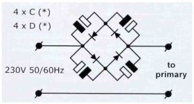
You only need some diodes and two low voltage, high capacity electrolytics to make your own DC blocker. Not very expensive. Throw in a mains in and output and you can test any of your amps without DC.
Or, ask eBay: https://www.ebay.de/itm/334875452528
Or, ask eBay: https://www.ebay.de/itm/334875452528
It depends on how much DC offset we are talking about. There are various styles of transformers and not all of them need be insanely overdimensioned so as not require DC blockers under normal operating conditions. Torroids happen to be be easy to design near the limits of flux saturation is all. Its not too hard to make them more like other normal transformers in terms of saturation headroom.
The main difference between toroids and other types, like EI is that the magnetic circuit is perfectly closed: there are no parasitic gaps, unlike other types of construction.
This reduces the magnetizing current, which is a good thing, but it also makes them oversenstive to any DC
This reduces the magnetizing current, which is a good thing, but it also makes them oversenstive to any DC
Seems to me if we compare a torroid and a R-core both formed out of mild transformer steel, the main difference in relation to DC tolerance is the core geometry. A R-core has a longer magnetic circuit path for same winding window area. The longer flux path has the effect of reducing flux density which gives more core saturation headroom. A circular geometry is the worst possible case. To think of it another way, if we took a torroid and squished it down into an oval shape, as we continue to squish it the winding window area would get smaller and smaller relative the magnetic circuit path length (which would remain more or less the same). At a limit there would be no space for copper windings, so it would be impossible to saturate the core. As we approach the limit, the saturation headroom has to go up since we can't get enough copper in the window to drive the core very hard.
Last edited:
Be better to actually test the cores and plot the B-H graph for them to see what differences there are. Leakage inductance may be important, not sure the ratio of magnetic path length to area is since you would normally adjust the number of windings and core size to match the inductance and power you require. Larger cores have larger A/L for the same geometry.
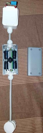
I made test sample DC blocker according to this schematic, obtained from the manufacturer of the toroidal transformer (650VA 40-0-40V AC wound on the core for 800VA). Unfortunately, it has a bad effect on the sound, a real shame. I solved the occasional increased mechanical hum by adding more #5mm rubber washers below and above the transformer, and just slightly tightening the retaining nut.You only need some diodes and two low voltage, high capacity electrolytics to make your own DC blocker. Not very expensive. Throw in a mains in and output and you can test any of your amps without DC.
Or, ask eBay: https://www.ebay.de/itm/334875452528
Attachments
Mark, with the very greatest respect this is just nonsense. If a DC blocker is affecting amplifier’ sound’ then either the DC blocker is at fault or there are serious questions about the amplifier.The problem with DC blockers is they can affect the sound of an amplifie
I didn’t say larger diameter either. I said bigger.
The problem with big toroids is the primary DC resistance is very low just 1 or 2 ohms and a net DC offset mean large DC currents are flowing in the primary winding.
In any event, I get my supplier to set the peak flux density at 1T rather than the more normal 1.3T most commercial grade toroids are wound at. This oversizes the core a bit, but it helps along with the DC blocker to ensure my amps never suffer from transformer ’growling’ or any other mechanical noise.
Last edited:

The transformer was made at 1T. Maybe I should have put bigger capacitors for the DC blocker. But this one, as it is made (4x4700uF 25V caps and 10A graetz bridge), has a negative effect on the amplifier sound. It's like taking something out of his life. The amp is vintage, LEACH LOW TIM. It is arranged properly and has served me well for a long time. Otherwise, it happens that there is 2-3V DC on the network, and the sine is not quite regular, it obviously contains harmonics.
My thoughts are going in the direction of building another DC blocker with some big capacitors (22000uF and above bypassed with a few hundred uF motor run PP caps. ) or getting some strong split transformer on EI core with a slot (1-1.5kW). A split transformer is quite an expensive option.
My thoughts are going in the direction of building another DC blocker with some big capacitors (22000uF and above bypassed with a few hundred uF motor run PP caps. ) or getting some strong split transformer on EI core with a slot (1-1.5kW). A split transformer is quite an expensive option.
Last edited:
Bonsai, with all due respect to you, sir, you haven't heard the resolution of my speakers. Someone who visited my house a couple of times described what can be heard: https://www.diyaudio.com/community/threads/dac-recommendation.376015/post-7560022Mark, with the very greatest respect this is just nonsense. If a DC blocker is affecting amplifier’ sound’ then either the DC blocker is at fault or there are serious questions about the amplifier.
Also, a quote from me in another thread:
...Years ago I reported that it has audible problems starting at midrange frequencies and extending up through higher frequencies. However I got some arguments from other people who didn't hear the issue with D90. Maybe there are thresholds of audibility for lots of different things. For people who are in the less sensitive 50% of a particular audibility threshold bell curve, the reality for them may tend to be that some problems do not exist or are not important.
https://www.diyaudio.com/community/threads/discrete-fpga-dac-project.407618/post-7572481
Thus, nonsense for you may not be nonsense in absolute terms
However, on the issue of low DC resistance and correspondingly higher currents, we agree that can be a problem.
On the topic of torroidal power transformers, Pass Labs uses one in HPA-1. It does not include a DC blocker. However, Pass Labs reported that they went through six prototyping iterations on the power transformer before arriving at one with a sound they they found satisfactory.
Last edited:
Mark, you have been challenged a number of times by lots of folks across the years on statements you have made about what is audible and what is not and you always fall back on 'but you haven't heard my speakers'.
Let's assume you are right. What is the mechanism that affects an amplifier so badly, that inserting a well-designed DC blocker on the primary side of the transformer makes it audible?
Let's assume you are right. What is the mechanism that affects an amplifier so badly, that inserting a well-designed DC blocker on the primary side of the transformer makes it audible?
You have placed the capacitors in series across the diodes so the 4700uF is effective 2350uF. It is better as someone has said in an earlier post to just use 2 capacitors.I made test sample DC blocker according to this schematic, obtained from the manufacturer of the toroidal transformer (650VA 40-0-40V AC wound on the core for 800VA). Unfortunately, it has a bad effect on the sound, a real shame. I solved the occasional increased mechanical hum by adding more #5mm rubber washers below and above the transformer, and just slightly tightening the retaining nut.
Bonsai, I didn't use the word "badly." There is a difference between bad and audible. IME sometimes electrolytic caps used for coupling may produce some current noise. Not all caps seem to be the same in that regard. Presumably if a noise is generated it can be like other AC line noise that gets into an amp. According to Bill Whitlock, AC line noise problems can result in "veiled" and or "grainy" sound. Many people would have no way of telling if their system was veiled or not. Mostly that only becomes clear when a veil is removed.
BTW, its fine with me if people want and or need to use DC blockers. I only point out it might affect sound in unanticipated ways. Just something to be aware of, same as with many other non-idealities in the components we design with.
EDIT: Actually, I don't "always" mention my ESL speakers. Sometime I mention using $20 Amazon headphones. Other times in the past I have stated I was using NS-10 speakers. Please try not to exaggerate about things I have described in different contexts.
Last edited:
Mark, if you make a statement like 'oscillation will cause a change in sound in the amplifier' one is readily able to understand that situation because it will be 100% measurable.
If you say a [decent] DC blocker (impedance at 50 Hz <350milli Ohms, or a fraction of the AC loop impedance if the primary impedance is included) in the primary side of the transformer may be audible, you can only make that statement with DBT to back it up, otherwise, it remains an opinion at best and conjecture at worst. There is no current noise from an electrolytic - there is EM radiation if not placed correctly or with a sloppy PCB layout, yes.
The problem with this sort of thing is that some guy building amps and working hard to optimize his system but with little technical knowledge will seize on your statement, and next thing DC blockers are out, and oversize 40 lb transformers are in. When I came to audio, I chased my tail for 2 or 3 years trying to make sense of what in the final analysis were just opinions and not backed up by solid technical evidence. Only when I stepped away from that stuff did I finally begin to make progress.
Then how do you account for the bright, grainy sound of Panasonic FM? You telling me that's not obvious? Or is the quote above your personal opinion only?There is no current noise from an electrolytic...
Regarding measurable, well, you can go complain to Bill Whitlock for saying AC line noise can cause "veiled" sound.
Regarding your concern for the guy trying to build an amp, if all he has is a sound card, he will optimize for distortion and noise. You and I both know its a problem. Give him a scope and teach him how to use it and now he can look for more problems. Teach him how to listen, and he may be able to solve some problems for which there are no simple measurements. Leave him on his own to learn how to do any of the above stuff and he is liable to make mistakes. IOW, listening is a skill like using a scope or a sound card. The mistake people make is to think its not a skill that has to be learned, practiced, and tested. Its also necessary to have trained people on your team who can help with the skilled listening.
Regarding DC blockers, they are not out. Look, you know transistor junctions can act as demodulators, right? Does that mean to you I am saying transistors are out? No!
Last edited:
- Home
- Amplifiers
- Power Supplies
- magnetic shielding/how to defeat hum-pickup