
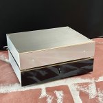
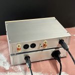
Low res shop shots....finished cases.
Loving the sound! No complaints....I won't know anything in the way of comparisons until I switch back to another amp....can't wait to listen to more records though... what more could you want?

Loving the sound! No complaints....I won't know anything in the way of comparisons until I switch back to another amp....can't wait to listen to more records though... what more could you want?
Attachments

Finished the project power supply and have been using that instead of the lab power supply, and must say - this is a quiet, beautiful sounding phono preamp. Very clean, great detail and separation, frequency range sounds excellent, and very quiet. Really one of my best phono preamps, and I've got lots.
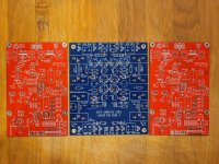
I drilled holes for the red/green diodes, but kept them on the board and just put in clear plastic windows. Subtle, but still able to observe both rail diodes when desired.
Kudos to Wayne for a lovely design!

I drilled holes for the red/green diodes, but kept them on the board and just put in clear plastic windows. Subtle, but still able to observe both rail diodes when desired.
Kudos to Wayne for a lovely design!
Hello All,
I am still playing with the P3 input stage assembled on a a breadboard and the the power supply.
This thing is assembled without the LM7815 and without the jfets. There is a 530 ohm resistor in place of the jfets.
The intention was to measure the PSRR of the capacitor multiplier. I did not make it that far.
There are the 60hZ, 120hZ, 180hZ and on up power supply ripples remaining down stream of the capacitor multiplier.
See the attached power supply FFT plot below.
Other people are completing the P3 with reports of quality sound.
What I see in the FFT plot is ear to the speaker noise and the need for more filtering.
Thanks DT
When you put the JFETs in, the PSRR will change by the amplification of the first stage.
The three-legged regulators will knock down the transmission of the LF by 60dB at least and the cap multiplier will reduce the noise.
Hello,
One modular piece at a time I am putting this thing together with measurements along the way.
I am using 96k FFT length and three averages to peek at the noise floor. Plus looking at PSRR.
Anyone have a FFT of the performance of the as specified P3?
Thanks DT
What I see in the FFT plot is ear to the speaker noise and the need for more filtering.
This reminds me of something...
The noise performance of course depends on the non included power supply.
When I run my system wide open I do indeed get ear to the speaker noise. Everything in one box.
At normal listening levels it isn’t there. I don’t know how much is supply and how much is pick up.
When I run my system wide open I do indeed get ear to the speaker noise. Everything in one box.
At normal listening levels it isn’t there. I don’t know how much is supply and how much is pick up.

The noise performance of course depends on the non included power supply.
When I run my system wide open I do indeed get ear to the speaker noise. Everything in one box.
At normal listening levels it isn’t there. I don’t know how much is supply and how much is pick up.
@wayne ,
Props to you for sharing your P3 with us.
It is raining here in NorCal so I poke and measure stuff. I gave up on arc welders and 600VDC power supplies.
All Just For Fun!
DT
Just started on a LM7815 breadboard module to see what happens in the quest to reduce ripple.
I can see that most builds use screened wire as signal cable.
My intention is to use twisted AWG30 vintage wirewrap cable. Assume this is fine even that the signals are very "weak" from the cartridge?
I wonder what ZM use to wirestrip this kind of wire. My Stripax does on work on this slippery surface and the very old fashioned tool with an adjustment screw seems not the best either. I have a dedicated wirewrap stripper for AWG24 and those also exist for AWG30 but are a bit expensive.
Maybe ZM just use a "Side Cutter"?
for finest things I'm using - dunno proper name on English - side stripper pliers, those with several "holes" increasing in size
though, couldn't find with small enough smallest hole for my needs, so I just fine-filed nose to adjust how much jaws are closing, thus hole getting small enough
presto
input wires for MC and MM - better safe than sorry - take nice coax cable ......... if not too thick and not too long, contribution in overall scheme is negligent, while safer to hum Gremlins than twisted pair
though, if build is clean, twisted pair is perfectly OK

- Home
- Amplifiers
- Pass Labs
- Pearl 3 Burning Amp 2023