Depends on chassis... the Triad split bobbin will not fit in a 1U. The blue 15VA Talema and Amgis will.
I'm using Talema 70053K in the guide.
I'm using Talema 70053K in the guide.
See the attached Pearl 3 Build Document.
This will be something that goes along with the illustrated, step-by-step build guide that Jim "6L6" is currently preparing.
Thanks again to Wayne for this design and the technical input on this document! Thank you to Jim and Greg "GKTAUDIO" for the collaboration and review of this document!!!
Nice job... two comments...
(1) How do you select 47K? It's not clear.
(2) I would recommend that a table be inserted for the gain ( makes life a lot simpler )... BTW, IMHO, a preamp of this caliber should at least have three gain settings, not just two.
| cartridge | Gain ( SE/Balanced ) | R9/R22 |
| 0.5mV | 70 / 76 dB | 2K2 |
| 1.0mV | ?????? | ????? |
| 5.0mV | 49 / 55 dB | 220R |
One question:
(1) Are the singled ended and balanced outputs enabled concurrently?

(1) How do you select 47K? It's not clear.
That's simple - don't turn on any of the resistor DIP switches. It's always on. Every resistor on the DIP is smaller and placed in parallel.
(2) ... ... BTW, IMHO, a preamp of this caliber should at least have three gain settings, not just two.
It's a great opportunity to design your own PCB with that functionality! Please post the Gerbers here when you have it completed and tested.
(1) Are the singled ended and balanced outputs enabled concurrently?
Yes, if you stuff the DRV135, of course.
Last edited:

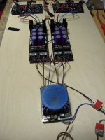
Example PSU using the included circuit board. This is built with the parts similar or identical to those listed in the build document.

That's simple - don't turn on any of the resistor DIP switches. It's always on. Every resistor on the DIP is smaller and placed in parallel.
It's a great opportunity to design your own PCB with that functionality! Please post the Gerbers here when you have it completed and tested.
Yes, if you stuff the DRV135, of course.
I reviewed the document as I normally review any such engineering document in a peer review. Trying to look for areas that might be incomplete, imprecise, confusing or plain wrong. Note I wasn't looking for missing commas, terrible grammar, etc...
It's pretty good, my comments were basically the need for some clarification... The writer, Randy, obviously knows what he wrote about, but what happens in many such cases, the writer forgets to make explicit what he/she considers implicit. Readers may not be be so knowledgeable so a simple additional clarification serves greatly to expand the usefulness of such documents.
As far as not using any of the DIP switches to achieve a 47K load... I looked hard at the provided tables but I didn't see such an option. If it was, then it wasn't obvious.
I did bring out two comments, outside the scope of the doc, As it turns out, you really don't need to use the DIPs and you don't need to create a new PCB... just move the switching out from the board... like on a rotary switch of sorts.
You might note that an introduction and a simple usage would be nice to have, but I'm not quite sure that is was within the scope of Randy's effort, so I didn't bring it up.
There... in a peer review, we may be seemingly cruel to each other, but it's always professional, helping each other and afterwards we go for lunch and drink a beer.
I think I'll have another Lagunitas Maximus tonight.
PS: interestingly enough, has the form factor to enable both outputs concurrently described anywhere? I know you've written about it, but has it been explicitly defined in a build or user's guide?
As far as not using any of the DIP switches to achieve a 47K load... I looked hard at the provided tables but I didn't see such an option. If it was, then it wasn't obvious.
It’s right there in the resistive loading table on pg15…
PS: interestingly enough, has the form factor to enable both outputs concurrently described anywhere? I know you've written about it, but has it been explicitly defined in a build or user's guide?
Ah! That’s a good point, and no, I don’t think it’s been mentioned per se… I’ll be sure to say something in the guide and article.
One of the neat features of the line driver is that it’s a fully contained IC… it looks at the SE output and takes care of the rest, converting to differential and levels the signal to someting appropriate for balanced connections. The SE output doesn't even know it’s there. So if it’s installed, the XLR output is always ‘on’.
@cubicincher
That's what I've been thinking too...
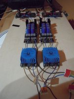
What all is populating your boards? Are those pre-regulators at the far end?
That's what I've been thinking too...
What all is populating your boards? Are those pre-regulators at the far end?
Thank you, Cubicincher.
I've considered the same thing - even mounting the individual phono boards in their own chassis with an air gap, but common faceplate/back panel. Cuz, why not?
I've considered the same thing - even mounting the individual phono boards in their own chassis with an air gap, but common faceplate/back panel. Cuz, why not?
@mhenschel:
You are right, it is a simple old-school PSU with fullbridge-rectifiers (MUR860), followed by a CRCRC-filter, followed by adjustable regulators (LT10857LT1033).
But this solution has the disadvantage, that the regulators are farther away from the PEARL 3 - boards... Hmmm 🤔
Waynes solution with the regulators on the PEARL 3 boards is in my opinion better. But I had these PSU-boards, so...
Mark Johnsons UDP3 is also a very interesting approach.
Greets
Dirk
@cubicincher
since you have the boards... just set the PSU output voltage to whatever Wayne's boards need -- perhaps the minimum of 17V -- to make 'em run well and to generate the least heat.
I'm considering this approach because of the unusual enclosure (with no or little ventilation).
since you have the boards... just set the PSU output voltage to whatever Wayne's boards need -- perhaps the minimum of 17V -- to make 'em run well and to generate the least heat.
I'm considering this approach because of the unusual enclosure (with no or little ventilation).
It’s right there in the resistive loading table on pg15…
View attachment 1241880
Ah! That’s a good point, and no, I don’t think it’s been mentioned per se… I’ll be sure to say something in the guide and article.
One of the neat features of the line driver is that it’s a fully contained IC… it looks at the SE output and takes care of the rest, converting to differential and levels the signal to someting appropriate for balanced connections. The SE output doesn't even know it’s there. So if it’s installed, the XLR output is always ‘on’.
OK. so you can reject that one comment about 47K loading.... Perhaps... instead of blank, it ought to say "OFF"? But know I'm grasping for straws... I guess you can let it be.
Pass me another beer... it's Sunday AFTER noon in the West Coast.
The weather is in the low 70s, sun is out... it's 9% IPA Time. ( I'm not allow to smoke for a week after the wisdom tooth pull... ratz... no cigars in this fine day ).
Here are a couple of distortion measurements of my Pearl 3 with remote power supply. The first shows the performance with the power supply 6 feet from the preamp, and the second is with the power supply box sitting right on top of the preamp. My Q403 is new to me - have only used it 3 times before, and only with power amplifiers, so I'm not sure if I've got the settings optimized. Oscillator input was set to 1.99mVrms for all tests, corresponding closely to my MC cartridge.


For comparison, here is an image of an iFi Phono preamp with remote wall wart. I tested it with a reverse RIAA board (Hagerman), and without.


For comparison, here is an image of an iFi Phono preamp with remote wall wart. I tested it with a reverse RIAA board (Hagerman), and without.
Here are a couple of distortion measurements of my Pearl 3 with remote power supply. The first shows the performance with the power supply 6 feet from the preamp, and the second is with the power supply box sitting right on top of the preamp. My Q403 is new to me - have only used it 3 times before, and only with power amplifiers, so I'm not sure if I've got the settings optimized. Oscillator input was set to 1.99mVrms for all tests, corresponding closely to my MC cartridge.
Hello,
I like what you are doing with the QA403 P3 measurements.
I revisited the P3 input stage noise measurements. I found that the bench power supply interfered with balance input measurements. Single end input to the analyzer works out much better.
Included this time is the LM7815 regulator. the added regulator helps reduce the noise measurements just a couple of dB's.
Next round I will add the jfets.
My impression so far is that much or most of the 60Hz on the FFT is leaking in somewhere.
As @wayne tells us 1 part per million is -120dB's. a Small leak may show up big on the FFT.
So we will watch to see what happens to the 60Hz spike, will it stay the same or amplify with the added jfet amplification.
See the attached FFT below.
Thanks DT
- Home
- Amplifiers
- Pass Labs
- Pearl 3 Burning Amp 2023