Odd aproach.
Like buying a high performance car, replacing the big brakes with small ones, removing the high performance engine and replacing it with a lower-output motor, then measuring the poorer performance, and documenting it on the internet.
Might be more useful to the project to measure with the preamp and power supply built as designed, but measuring the differences with the range of different components suggested in the design - JFETs, op amps, etc.
Jim, yup that's it
having Katapult (like) ones too, but that type is really for heavier gauge
having Katapult (like) ones too, but that type is really for heavier gauge

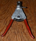
I have the Katapult, it has jaws that work wonderfully on 20ga (0.81mm) teflon wire, and everyting bigger.
Very handy tool.
For smaller diameter, the pliers-type in the other link works beautifully.
Very handy tool.
For smaller diameter, the pliers-type in the other link works beautifully.
I will look for the Kleintool for the small gauge wires.
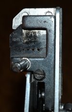
I also have some of the "Katapult type" strippers. In my case those are vintage Belzer tools (German).
The one which takes smallest gauges shown at picture. Maybe those exist for even smaller gauges.
The dedicated WW-tool I have is for AWG24 only but also exists for AWG30 and can be purchased new. But they don't give them away as gifts. Same applies for this Erem (Weller) tool which I have considered to have as "Christmas gift":
https://www.weller-tools.com/us/en/precision-tools/products/pliers/552s
The Klein-tool is a bit more price-friendly and ZM's approach.
Attachments
I use these Greenlee 1917-SS cutters for wire down to 26/28 ga., and it works really well with Teflon insulated wire - nice, clean cuts with no/minimal wire nicks (watch the wire size to cutter opening and no nicks).

A cheaper way is to soften the insulation with a cigarette lighter - not TOO much - and to use thumbnail against 1st finger - and pull gently!👍👎
Also if it is "teflon" (PTFE) based insulation? 🙂 ....that is the case with my vintage wirewrap 30 AWG cables....
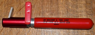
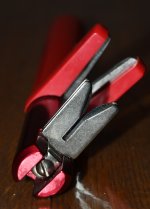
I just ordered this one at Amazon to try it out:
https://www.amazon.com/dp/B000XEUPMQ/ref=pe_386300_440135490_TE_simp_item_image?th=1
I just ordered this one at Amazon to try it out:
https://www.amazon.com/dp/B000XEUPMQ/ref=pe_386300_440135490_TE_simp_item_image?th=1
@MEPER
Lots of people seem to use light tightly-twisted-pair wiring that resembles pairs from CAT Ethernet cables.
Twisted seems logical.
Back in the old days I had some foil-shielded twisted pair cabling by Belden -- 8451. it had stranded tinned copper conductors, polypropylene insulation and a bare drain wire. A reasonable configuration.
Odd aproach.
Like buying a high performance car, replacing the big brakes with small ones, removing the high performance engine and replacing it with a lower-output motor, then measuring the poorer performance, and documenting it on the internet.
Might be more useful to the project to measure with the preamp and power supply built as designed, but measuring the differences with the range of different components suggested in the design - JFETs, op amps, etc.
Odd that you should take exception.
Using the experimental modules on the bench allows holding some variables constant while isolating other to observe their performance.
See the 1st Stage breadboard photo below.
Note that the capacitors can be quickly swapped out for others. The current through the breadboard can readily be changed by swapping out the load resistor. Also note that the Bipolar Junction Transistors can also easily be swapped out. I now have data for several NPN's.
The output stage breadboard will allow swapping Q9 and R27 in search of a distortion / noise sweet spot.
I do this for fun. Props to @wayne .
Simulating with solder I like that. I just have an old AP system one here, the new 500 series is at the factory so FFT isn't available currently.
Given a gain of 90 dB on the low frequencies and may 10 dB on a pre coupled with 30dB on a power amp and you have a gain of over three million at the bottom end.
Given a gain of 90 dB on the low frequencies and may 10 dB on a pre coupled with 30dB on a power amp and you have a gain of over three million at the bottom end.
EDIT: This guide has been superseded by ver1.0b, see post #1020 https://www.diyaudio.com/community/threads/pearl-3-burning-amp-2023.404054/post-7533872
See the attached Pearl 3 Build Document.
This will be something that goes along with the illustrated, step-by-step build guide that Jim "6L6" is currently preparing.
Thanks again to Wayne for this design and the technical input on this document! Thank you to Jim and Greg "GKTAUDIO" for the collaboration and review of this document!!!
Attachments
Last edited by a moderator:
Fantastic!!
If you have any interest in building Pearl 3, this is the document to read!
If you have any interest in building Pearl 3, this is the document to read!
This really great. With a document like this I may be able to build this thing without doing too much damage to myself or the Northeast US Power Grid.See the attached Pearl 3 Build Document.
This will be something that goes along with the illustrated, step-by-step build guide that Jim "6L6" is currently preparing.
Thanks again to Wayne for this design and the technical input on this document! Thank you to Jim and Greg "GKTAUDIO" for the collaboration and review of this document!!!
I continue to learn from all of you every day. And I'm having fun too!
Yep. That was me. A little problem with trying to run a dynaco st-70 by attaching it to the third rail of the #2 train. But there was a benefit when the bars all realized their power was out so they started selling beers at 1/2 price. Good times in the Village... Just don't let on you know whom it was. I have a respectable job now...😛
@rhthatcher
minor typo...
on page 11, in the 15VA option parentheses shouldn't it say "if 12VA is out of stock"? or 25VA??
minor typo...
on page 11, in the 15VA option parentheses shouldn't it say "if 12VA is out of stock"? or 25VA??
RIAA chassis kit configuration.

Yes, I need to trim the red power umbilical a little, it's a touch long.
Yes, I need to trim the red power umbilical a little, it's a touch long.
so the first choice is the 25VA unit?
last choice, the 12VA split bobbin? or??
Suitable Triads then:
FS28-700-C2. (20VA)
FS28-420-C2 (12VA)... perfect for a single channel.
last choice, the 12VA split bobbin? or??
Suitable Triads then:
FS28-700-C2. (20VA)
FS28-420-C2 (12VA)... perfect for a single channel.
- Home
- Amplifiers
- Pass Labs
- Pearl 3 Burning Amp 2023