You don't need to get to fancy IMO, this amp have a superb PSRR, even point to point with a KBPC3510 (a la GFA555II) with a decent wire will work.What can I use?
Toroidy also offers custom made transformer. Just send them an email. I bought one with four separate windings for good price, and I'm quite happy with it. For next time.Yeah just ordered. No plan, I was told i need a 50-0-50 so that's what i ordered
This toroidal already is a custom build and I assume they build it as requested by the customer.
What’s the HP filtering cutoff frequency for C1? Is there a formula I can’t use?
I know everyone in the thread loves MKP but I’m curious to try something else 🙂
I know everyone in the thread loves MKP but I’m curious to try something else 🙂

Could someone please help me out with the above query.EF3-3 or EF3-4 ? Please suggest for Polk Legend L600
Dear friends,
I do have a pair of Wolverine EF3-3 boards procured from @fireanimal, and yet start working on it. I would like to pair the Wolverine with my Polk speakers which are rated at 4 Ohms(3.3 Ohms minimum) and 86db sensitivity. The Polk dealer suggested me to pair the speakers with a high current 2 Ohms capable amplifier.
So which one should be the ideal output choice, 3 or 4 pair? I can purchase EF3-4 boards if there is a real benefit out of it. Your response would be much appreciated.
Transformer: 40-0-40 400VA per channel or 45-0-45 500VA per channel
Output transistors: OnSemi 2sc5200/2sa1943 or OnSemi MJL3281/MJL1302
Regards
Sha
Thanks
Sha
What’s the HP filtering cutoff frequency for C1? Is there a formula I can’t use?
I know everyone in the thread loves MKP but I’m curious to try something else 🙂
1/(2piRC)
How do i wire this up?
Hi guys, we (the wolverine team) has seen this unfortunate oversight. While not the end of the world I'm sure you'd have preferred to have ordered a dual secondary transformer not that you are aware of the different transformer topologies.yeah, not end of the world, you need to use this power supply topology with a centre tapped secondary.
We have put some information together and will update the build guide and BOM accordingly.
Hopefully this will enable future builders to select the appropriate transformer.
I have this board, or you can find it in the 100W amp thread on this forum. It allows you to use Dual or Center-tapped secondaries. I have a few left from a previous order, if you want one to try out, PM me.How do i wire this up? Two grays to soft start then a blue to each side of the rectifier board? Jumper red to both sides of the rectifier board? Ground the green/yellow?
I assume that you will use one transformer per channel, in which case both of the rectifier circuits will be of the single rectifier, center tap ground type. Sorry this took a while to get back to you. I've been having cataract surgery and can just today see the computer well.Am not able to quote mhuth1776. Will look into it. I am planning to use two transformers as I have two of them. Should I still consider the different wiring.
Hi Guys,
The Build Guide has been updated, the current revision is now 41.
Please check your Dropbox folder or post #1 of this thread for the latest version.
Revisions are noted at the end of the document.
The BOM has also been updated, the latest version is 2023 October 7
Don't worry there are no component changes. Some information was added in relation to transformer selection.
See the revisions noted at the end of the document for details.
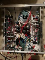
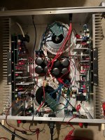
Finished Amp... It is very quiet and sound great.
I used MJL1302AG/3281AG for the finals...
I installed larger heatsinks... 4.75 in x 14.56 in.
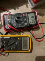
DC offset = 0.00
ripple on speaker outputs = 1mv
TP1 TP2 = 5.00v
After letting sit at idle (over an hour) with bias set to about 40 to 45mV, the heatsinks temps were about 80 deg F.
When I put the cover on the chassis, the bias voltage went down to about 30mV.
So if I understand correctly, with the cover on, I adjusted bias back to 44mV.
With it set like this and I remove the cover, the bias starts going up to about 55 to 60mV.
Is this OK?
I used MJL1302AG/3281AG for the finals...
I installed larger heatsinks... 4.75 in x 14.56 in.
DC offset = 0.00
ripple on speaker outputs = 1mv
TP1 TP2 = 5.00v
After letting sit at idle (over an hour) with bias set to about 40 to 45mV, the heatsinks temps were about 80 deg F.
When I put the cover on the chassis, the bias voltage went down to about 30mV.
So if I understand correctly, with the cover on, I adjusted bias back to 44mV.
With it set like this and I remove the cover, the bias starts going up to about 55 to 60mV.
Is this OK?
Attachments

Leave it for a while whilst monitoring the bias.
See what it settles down to after an hour or so.
This step takes a little while
- Dan
See what it settles down to after an hour or so.
This step takes a little while
- Dan
Folks:
I'm very happy to report that my parents' Wolverine amplifier, which suffered a failure after a hard year's work (they play that amp about 10 hours a day at a not inconsiderable volume), has been repaired. Frankly, my diagnostic skills stink and I have a tendency to freak out when trying to effect a repair, mostly because I have no idea what to do. That's why I love the diyAudio community so much -- there invariably is a good-hearted soul who can point me in the right direction. In this case that person was stuartmp, who spent a lot of time offering smart, clear-headed guidance and support to this old dope. Big kudos to Stuart and the rest of the Wolverine design team for not just offering their remarkable design to the community but also in their willingness to spend valuable time supporting intrepid Wolverine builders.
Seriously, I am very grateful.
Regards,
Scott
Attachments

fireanimal:
It might have been as simple as a cold solder joint. Stuart observed that I had only soldered on one side of the pcbs and had me reflow every existing joint as well as add solder to the other side. It's also possible the problem stemmed from the 10mm standoffs I had installed between the IPS and OPS boards; replacing them with 8mm units, which put the upper and lower pin headers into near contact, may have also helped.
Regards,
Scott
- Home
- Amplifiers
- Solid State
- DIY Class A/B Amp The "Wolverine" build thread