Yeah, thats what I figured. The 6 op for that case.Case is too small , 6 OP just fits.
Then you would need that $200 dissapante DIYA chassis and 150$ antek , that's what I avoided.
OS
Maybe in the future, if I can source a bigger case, then maybe I will shoot for the $150 antek and the 8 op.
You know whats funny. I’ve drooled over the neurochrome 686 which has the 6 op per board. TBH while I think its great, that is definitely out of my price range for a build.
After seeing the actual build guide and the youtube video, I am getting pumped for this build!

I'm actually going to use the little outputs (NJWxxxx TO-3P) for my little case , TO-264 would requireYeah, thats what I figured. The 6 op for that case.
trimming 10mm off the top cover.
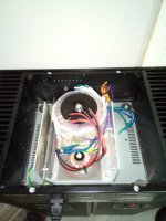
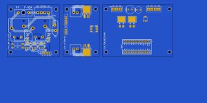
I have the trafo's on one 1/8" aluminum sub-chassis (below). It will have my PS , Arduino , protection/soft start.
just 4 holes/bolts on the bottom cover and I can pull the whole module right out.
Don't make fun of my 500VA power supply - I'll be loud !
Just waiting for more boards - I might just fire it up without the protection.
OS
Attachments
Last edited:
Ha! Absolutely! Your ears or your speakers might give up before the amp, unless you are running the most inefficient speakers on planet earth. So far its looking great. Do you think you will run into any issues if you don’t add the protection before hand? Also, are you gonna use the same connectors in the back of the case? Of are you going to put some regular binding post?Don't make fun of my 500VA power supply - I'll be loud !
Just waiting for more boards - I might just fire it up without the protection.
Can be solved with gravity and kinetic energy. Apply some flux and new solder, heat the spot up and instantly tap the pcb with its side on the bench. Use 60Sn/40Pb.Can this bridge be fixed?
Drill 6 holes - 2 for inputs (well separated , 4 in the middle for the speakers. I'll mount the fancy SS relay right on the rear.Of are you going to put some regular binding post?
Wolverine is safe ... after running on the bench for a day , I'll hook my better speakers up.
OS
Check that all of the drivers/pre-drivers are oriented correctly along with the bias transistors. It would be easy to put one or more of them in backwards. Same goes for the cap multipliers - Q101,102. If you have a bench supply that will do current limiting, then lose the fuses and ramp up the rail slowly, watching the current draw. Without the output transistors, the circuit draws less than 40ma. Then you can check some of the circuit voltages against the schematic.
Make sure that J103 is installed and that you have the feedback path correctly jumpered on the bottom. There was at least one solder jumper missing or misplaced from the early build guides. One of the required path 1 jumpers is not identified clearly on the silkscreen. Also check the heatsinks and transistor leads to ensure there are no shorts to the heatsinks from mounting.
Your meters show that CCS1 is in the ballpark, as is the bias offset on the second meter.
Other than that, see the troubleshooting section of the build guide. In particular, use the procedures to bring the IPS and EF3 up separately. Given that neither IPS works, then start with the EF3. It would, of course, be possible to make the same transistor installation mistake on both of the IPSs.
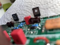
They could be small body and they got lost in the video compression, hard to tell from videos unless filmed, uploaded losslessly to cloud server and link to video is shared. The only way to do videos IMO
Yeah, I can't really tell either, although it is clear that the input degeneration resistors are surface mount. It looks a lot like my version with the surface mount resistors at the current mirrors. Those are quite small. On zooming, I'm pretty sure that the resistors are in place. I think I see the solder when the contrast is boosted.
Last edited:
Nice! How does it sound? What speakers are you using??Drill 6 holes - 2 for inputs (well separated , 4 in the middle for the speakers. I'll mount the fancy SS relay right on the rear.
Wolverine is safe ... after running on the bench for a day , I'll hook my better speakers up.
OS
Thought I'd post up the measurements I took of my 4 pair build - not bad considering the only transistors I bothered to match were Q1/2 & 3/4.
Heres the loop back of my measurement rig - Laptop -> E30 (power is isolated from usb data) -> E1DA cosmos ADC -> laptop

So as you can see, not as good as @fireanimal or @danieljw 's rigs, but definitely enough for me to do a sanity check on my own amps.
Heres right channel 5W into 8R as installed final in chassis with lid on - the left channel looks distortion identical but there is slightly more 50hz mains noise due to the RCA input wiring running around the whole perimeter of the chassis.

Just crazy the distortion meets or exceeds that of the DAC. As usual, the real problem is noise. My thoughts on the sound of the amp have not changed, they can pry this from my cold dead hands. Love listening to it.
I can only hear the slightest hum with my ear almost literally touching the woofer (-power supply), and the tweeter is absolutely silent (-amp design)
So I'm gonna give it one of these:

No hum, no hiss, no distortion, just the music 😎
/s
Heres the loop back of my measurement rig - Laptop -> E30 (power is isolated from usb data) -> E1DA cosmos ADC -> laptop
So as you can see, not as good as @fireanimal or @danieljw 's rigs, but definitely enough for me to do a sanity check on my own amps.
Heres right channel 5W into 8R as installed final in chassis with lid on - the left channel looks distortion identical but there is slightly more 50hz mains noise due to the RCA input wiring running around the whole perimeter of the chassis.
Just crazy the distortion meets or exceeds that of the DAC. As usual, the real problem is noise. My thoughts on the sound of the amp have not changed, they can pry this from my cold dead hands. Love listening to it.
I can only hear the slightest hum with my ear almost literally touching the woofer (-power supply), and the tweeter is absolutely silent (-amp design)
So I'm gonna give it one of these:
No hum, no hiss, no distortion, just the music 😎
/s
Last edited:
I don't have that (stereo) one done yet. i'm still building it.Nice! How does it sound? What speakers are you using??
I do have one of the wolverines running a sub ! Wow , it can really belt out the watts.
I've built so many amps over the years , I know how it will sound ... no surprises here.
I'm more into reliability/durability , all 4 of my PPM designs sound about the same. under .001%
it hard to tell, PS size will determine the "kick" of the amp cranked up , as will having a higher rail voltage.
My OEM HK680 "runs out of steam" with too many peaks and it's smallish trafo "collapsing" the rails.
500VA does not collapse , my one wolverine can do 200+W all day @ 4R (on my sub).
I fully expect to have a 150W X 2 amp in my little case.
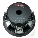
Speakers ? now - a 500W ULTRA 4R sub (below) in a 2.2cu ft box If I had more room ,
I'd buy 2 and build a pair of 3-ways (powered by wolverines). https://www.ebay.com/itm/133555744366 (6 left)
This speaker seem to be a perfect match for my EF3-3. Does not sound like a car audio sub - real snappy bass.
I also have some real powerful 8" dayton RS-225 2-ways , these will be my stereo speakers (along with the sub).
I moved on to 2.1 systems long ago.
OS
Attachments
I was explaining this to someone on the forum recently that the wolverine (and other PPM designs) ,that the semi noise floor is the limiting factorJust crazy the distortion meets or exceeds that of the DAC. As usual, the real problem is noise. My thoughts on the sound of the amp have not changed, they can pry this from my cold dead hands. Love listening to it.
<1 PPM. So , the only way to beat the wolverine would be to source "quieter" parts. It really doesn't matter at these levels.
Nice performance , BTW.
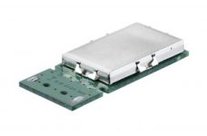
Edit - I'm going to start (full) shielding of the SMD versions of these amps. Halcro - here I come !! he he..
OS
Attachments
Last edited:
Great work!Thought I'd post up the measurements I took of my 4 pair build - not bad considering the only transistors I bothered to match were Q1/2 & 3/4.
Heres the loop back of my measurement rig - Laptop -> E30 (power is isolated from usb data) -> E1DA cosmos ADC -> laptop
View attachment 1216841
So as you can see, not as good as @fireanimal or @danieljw 's rigs, but definitely enough for me to do a sanity check on my own amps.
Heres right channel 5W into 8R as installed final in chassis with lid on - the left channel looks distortion identical but there is slightly more 50hz mains noise due to the RCA input wiring running around the whole perimeter of the chassis.
View attachment 1216843
Just crazy the distortion meets or exceeds that of the DAC. As usual, the real problem is noise. My thoughts on the sound of the amp have not changed, they can pry this from my cold dead hands. Love listening to it.
I can only hear the slightest hum with my ear almost literally touching the woofer (-power supply), and the tweeter is absolutely silent (-amp design)
So I'm gonna give it one of these:
View attachment 1216848
No hum, no hiss, no distortion, just the music 😎
/s
I have an E1DA Cosmos ADC now too they are a nice piece of equipment.
No, lowering the temperature is next step, shielding is only first step.I was explaining this to someone on the forum recently that the wolverine (and other PPM designs) ,that the semi noise floor is the limiting factor
<1 PPM. So , the only way to beat the wolverine would be to source "quieter" parts. It really doesn't matter at these levels.
Nice performance , BTW.
Edit - I'm going to start (full) shielding of the SMD versions of these amps. Halcro - here I come !! he he..
OS
low temp , oh yeah - ice cold IPS's. Liquid nitrogen ?? he he.No, lowering the temperature is next step, shielding is only first step.
PS - the Wolverine runs quite cool , I'm running 4ma CCS (instead of >5)
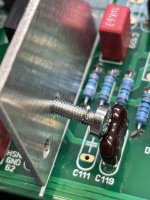
The heatsink is grounded. I don't see any insulator unless you removed it. The problem with insulators is there's always some clearance and the transistors holes has clearance to. Those two clearances accumulate and sometimes form a connection as things move around when you tighten up the screw. That's why I prefer kapton tape with a small holes pieced in it. Nothing moves and you won't have a short. In this situation I normally put a insulating washer in from the other side and trim it with a sharp hobby knife. That way the internal part of the hole is insulated.Consistency check was ok without voltage applied, but now there’s contact!
Easy to see on the screw, but not on the transistor.
Perhaps use a plastic screw on this one?
- Home
- Amplifiers
- Solid State
- DIY Class A/B Amp The "Wolverine" build thread