I had the exact same issue withthe terminal block and found that a plastic adjustment tool went right between the wires on the terminal block.

anyone have a lead on a couple pairs 2sc4883a & 1859a - also want to try the ksc3503e/ksa1381e for predrivers if avail - gonna go higher end fit out on this next 70V 4 pair build.
I just finjshed my wolverine boards yesterday and drilled and tapped 1 heatsink from my 5U case bought from diy audio store. I powered up module and connected cd player and i set dc offset and bias. I had honey badger in this case and an Antek 800va 8445 . I split board and have 4 10k caps for each side gives me 63 volts with amp running at moderate levels when pushed it drops to 61 at low frequencies. I couldnt resist so i powered up 1 badger 1 wolverine and had my daughter do blind listening test. I was not real surprised the wolverine was the one she picked after i made her sit (against her will) and listen to 3 songs. My own opinion is the same the wolverine is clearer on top end and reaches lower and hits harder at low frequency. It has been a 3 month journey and i tried every possible combination of transistors on input and driver output boards. They all worked not a huge difference between any of them which is a testament to the Great design and testing . A HUGE Thank You to ALL who worked so hard on this amplifier i will enjoy it for years to come and you have my sincere gratitude THANK YOU i love my new amp
Attachments

Same same. I have acquired a 50-0-50V 800VA toroid for my EF3-4 build. No doubt overkill but what a beautiful creation 😂
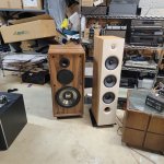
Yes it really sounds so good and smooth no harshness at All on top and low frequency response and slew rate are superb . I have only tested it on the old Cerwin Vega towers I bought 30yrs ago I need to finish my soft star and dc protection.I cannot wait to hear on the Focals sitting next to them the tweeters on the new focals are fantastic revealing and super smooth no fatigue from hours listening the Wolverine is going to make them really shine. I again Thank the entire Wolverine team what an accomplishment in DIY audio this rivals the best Amps from the best manufacturers in this business and that is something all of you should be proud of Thank You
Folks:
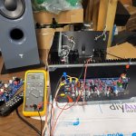
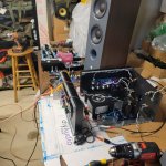
I'd be grateful for your help in diagnosing a problem with a Wolverine amp channel. I gave my parents an integrated amplifier almost exactly a year ago (see post #472 - https://www.diyaudio.com/community/...rine-build-thread.385920/page-24#post-7114011) and they've been thrilled with their new stereo until last week, when they told me that something was wrong. I visited them to swap out the Wolverine for their old amplifier (they need music about 10 hours a day) and am now trying to puzzle out what has failed. Lacking any engineering experience, it didn't take me long to find myself lost.
The problem is definitely in the Wolverine's right channel. It produces heavily distorted music at about 1/4 the volume of the left channel. The rest of the integrated amp is working properly. Before I start tearing the amp apart, it seemed best to consult with the experts.
Your help is very much appreciated!
Regards,
Scott
Attachments
This problem would be easily solved with a spare IPS.
Have you swapped the good IPS into the bad channel ?
Easy to run the EF3 separate . 22K - (V+ to PD+ and V- to ND-).
Most likely the IPS. Faulty EF3 , there would be NO volume on the bad channel.
OS
Have you swapped the good IPS into the bad channel ?
Easy to run the EF3 separate . 22K - (V+ to PD+ and V- to ND-).
Most likely the IPS. Faulty EF3 , there would be NO volume on the bad channel.
OS
ostripper:
Happy to try swapping the two IPS boards, but what is the likelihood that in doing so I will damage either the second IPS board (if the problem lies elsewhere) or the EF3 board?
I'm not trying to argue with you -- I simply want to prevent the problem from worsening. That said, if the IPS swap makes sense, I'll certainly do it.
Regards,
Scott
@SRMcGee If possible, please spend some time to find the fault. I'm not that much a fan of amps that misbehave after a year of use, but could be all sort of things since we're all on different levels in the world of DIY, ment in the best way (my level is roughly amateur into the knowledge of electronics)... Hopefully it's just a bad solderjoint, but if it is a faulty component it would be really nice to know witch one 🙂
Best regards
Best regards
Take a looj at the newest build guide, it has extensive information on testing the IPS and OPS boards seperatly and quite a bit of troubleshooting info that was not in the build guide when you built your Wolverine.
All good advice. I'll check the IPS board for a bad solder joint, review the latest build guide and, if the issue isn't apparent to me (let's give that a high probability) then swap the IPS boards. No matter what, I'll report back.
Thanks to all for the support!
Regards.
Thanks to all for the support!
Regards.
I just went through this, one channel went full rail voltage on the right channel. turned out to be the QHelp (KSC1845) - not saying that's your issue, bc you say you have distorted sound, I had nothing but -68Vdc.
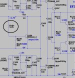
Agree with what others have said - start with the soldering and use a good magnifying glass (I circled a few to check, as well as look at entire amplifier for similar joints - you should see solder "wick up" to the top side of the joint). Once you are confident of the soldering, we can assist you if the problem persists.

Agree with what others have said - start with the soldering and use a good magnifying glass (I circled a few to check, as well as look at entire amplifier for similar joints - you should see solder "wick up" to the top side of the joint). Once you are confident of the soldering, we can assist you if the problem persists.
Check the EF3 by itself (without the IPS). Before you even do that , see if the V+/V- is present and correct. With the resistors I stated , you can even set the EF3 bias (without the IPS). This is one of the main reasons I design modular.ostripper:
Happy to try swapping the two IPS boards, but what is the likelihood that in doing so I will damage either the second IPS board (if the problem lies elsewhere) or the EF3 board?
I'm not trying to argue with you -- I simply want to prevent the problem from worsening. That said, if the IPS swap makes sense, I'll certainly do it.
Regards,
Scott
PS - I just built 2 of these EF3's ,added my IPS's with 2 X 27K. 22K = 5.5mA VAS ..... 27K 3.8mA VAS.
You can test the IPS (by itself) - PD+/ND- to 2 X 22K to NFB.
2014 , we did this with all the dozens of new IPS designs (Slewmaster).
OS
Update on my build.
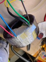
I reduced transformer voltage by taking out about 10 windings. Patient survived and voltage level is now 70,5VDC (no load). Hopefully the not 100% symmetrical secondary winding will cause any issues?!
When ordering boards I asked if it would be possible to get complete BOM. This to save time, reducing errors in purchase and getting the components that an expert uses 😊
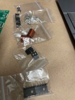
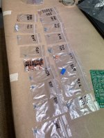
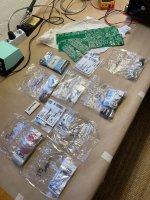
I'm thrilled and very grateful to @fireanimal who put together this incredible package - look at the pictures!!!
Everything sorted and marked, Transistors Q1-Q6 matched better than 0,1%. Legs pre-bent, output coil perfect wound, small heatsinks pre-drilled. Terminals, input cap, fuse holders - everything included!
Thanks again to @fireanimal and all other guys involved - hats off!
I reduced transformer voltage by taking out about 10 windings. Patient survived and voltage level is now 70,5VDC (no load). Hopefully the not 100% symmetrical secondary winding will cause any issues?!
When ordering boards I asked if it would be possible to get complete BOM. This to save time, reducing errors in purchase and getting the components that an expert uses 😊
I'm thrilled and very grateful to @fireanimal who put together this incredible package - look at the pictures!!!
Everything sorted and marked, Transistors Q1-Q6 matched better than 0,1%. Legs pre-bent, output coil perfect wound, small heatsinks pre-drilled. Terminals, input cap, fuse holders - everything included!
Thanks again to @fireanimal and all other guys involved - hats off!
Attachments
Hi Scott,I'd be grateful for your help in diagnosing a problem with a Wolverine amp channel
I'm sorry to hear that your currently experiencing a problem with your Wolverine build.
I appreciate the comments made by other members. Thanks for trying to help out guys 🙏
Looking at the photos and given that the amplifier is still working. Well sort of apart from the distortion as you mentioned it could quite possibly be a bad solder joint.
Its always preferable to ensure solder has flowed though each hole.
I usually place a quick dab of solder on top just top double check and neaten the joint up a little.
To reiterate what I'd look at to begin with I'd.
1. Pull both channels out and separate the IPS board from the output stage board. Then remove the output stage board from the heatsink.
2. I know that it's painful but go over each and every solder joint and refresh the solder joints ensuring a good connection as mentioned above.
3. Download the latest build guide attached to the first post or in your Dropbox folder and refer to the troubleshooting section. Then proceed to test each board individually.
4. If both board check out re assembly both channels with the ips boards in their original output stage board. You may have fix the issue if it was a bad solder joint.
5. If the problem remains please switch the ips boards and re check.
This should isolate which board has the issue.
6. Once this is known and with both channels on the bench I would download the latest schematic and start testing and confirming voltages as shown on the schematic. You can also use the working channel as a reference.
This should help you isolate or fix the problem. If you manage to isolate the issue or have any further information please post so we can try and assist you further.
Good luck 🤞
If you end up breaking it down on the bench, might pay to make the Q103/104 swap that was added too.
Good advice there I almost missed the 103 104 swap I did not check for updated build guide and did have them reversed.The updated info is Q103 to main heatsink and Q104 as ambient. I had tripin female socket which I used the leads to extend Q103 to heatsink it worked great did not have to solder just made sure they had solid connection with my Meter
What problem were builders having to implement the "Q103-Q104 swap" ?
I'm running a MJE340 as main Vbe (Q104). Running my subwoofer hard with my single running Wolverine ,
I thermally over-compensate by 10mA when real hot to the touch. 70mA cold /60mA super hot.
One simpler EF3's (like some 70's Sansui) , Q104 is the ONLY Vbe.
The Sansui (simple - below) , just overcompensates to be safe. RVbe /2.8K is the upper value that replaces Q103/R105-107.
Q103's only purpose is to redefine the Vbe ratio to compensate for the different driver vs output co-efficient.
With difficult loads the drivers will heat much more than with normal loads.
Build guide says (BD139) ?? They have a different co-efficient than the 340's.
Q103 as main Vbe would compensate by changing the ratio (up to a point) , then "run out of steam".
Q104 has WAY more effect on output bias.
Everything works fine for me with Q104 (on leads) to the HS and Q103 between the drivers.
Same as the previous Slewmaster
OS
Attachments
Thank you for detailed explanation of this I do not have your level of expertise and I welcome any knowledge that you share with us .I have enjoyed building my last 2 amplifiers and thanks to Everyone on the honey badger and wolverine willing to share their time and talents with us makes DIY Audio a great place to spend our limited time learning and enjoying some of the best sounding equipment these ears have Ever Heard .THANK YOU FOR THAT YOU HAVE MY SINCERE GRATITUDE
Hi Micheal,Thank you for detailed explanation of this
There was in fact an issue with the original implementation.
Please refer to post #2,057 using the following link Bias spreader implementation and those that proceed on the topic.
Thanks again for to @fireanimal, @jjs and @danieljw for their testing and dedication to actually testing and resolving this issue.
- Home
- Amplifiers
- Solid State
- DIY Class A/B Amp The "Wolverine" build thread