Hi Gary,Hi again prasi, is it worth changing the silk screen on your pcb for the value of C3 back to 220pF (was 47pF) as lineup has shown in post #49?
I will wait on your reply before I order my pcb's, thanks.
there is no need to change gerbers and silk again.
one can use 180p/200p/250p /220p from one's part bin.

The target max output is 9.5-10 Watt Class A into 8 Ohm.
It depends a bit on the actually supply voltage from the trafo.
A guess is +/-16 to +/-17 VDC rectified from transformer.
The trafo is of course 2x12VAC. Can be 100VA-200VA.
If both channels are driven by one and same trafo I should say we should use 200VA.
It depends a bit on the actually supply voltage from the trafo.
A guess is +/-16 to +/-17 VDC rectified from transformer.
The trafo is of course 2x12VAC. Can be 100VA-200VA.
If both channels are driven by one and same trafo I should say we should use 200VA.
Last edited:
How about
1) some RFI suppression at the input? R=220, C= 220pF
2) Some bulk decoupling for VCC,VEE? Prasi shows them in his schematic and layout.
3) emitter followers for U3,U6,U8
1) some RFI suppression at the input? R=220, C= 220pF
2) Some bulk decoupling for VCC,VEE? Prasi shows them in his schematic and layout.
3) emitter followers for U3,U6,U8
Thanks Vunce,Excellent compact layout Prasi!
Glad I waited, this version allows more chassis options for me.

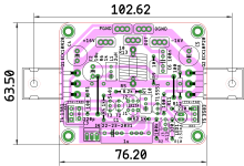
here are gerbers. It might be slightly challenging stuff for some, but for you , its simple.
and also diy pdf attached for thimios.
Attachments
-
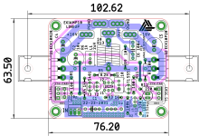 LINEUP-10W-LAY-OPT2.png174.9 KB · Views: 290
 -
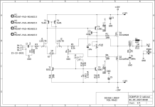 LINEUP-10W-SCH-OPT2.png79.8 KB · Views: 289
 -
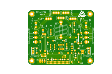 EXIAMP10-2-optional.png134 KB · Views: 281
 -
silk-as-seen-from-top-OPT2.pdf39.9 KB · Views: 159
-
copper-btm-as-seen-from-top-OPT2.pdf13.3 KB · Views: 155
-
EXIAMP10-2-optional_2023-09-05.zip243.3 KB · Views: 116
How well it behaves if loaded by a capacitor (say 10n), straight to the amp output, with everything else disconnected (Zobels, load, inductors etc.) ? If it is not able to handle at least 10n capacitive load it will IMHO be prone to oscillation when fully built, even with no capacitive loads present.
Capacitive load.
That is what the wirewound inductor is for. In the Zobel.
Don't think this will be a problem.
That is what the wirewound inductor is for. In the Zobel.
Don't think this will be a problem.
I have tested with a speaker model RLC load.
I had to add C5=10pF across the feedback resistor. And change C1=100pF.
This was done simuating with the oscilloscope.
Resulting squarewave at 1kHz can be seen in 2nd image.


I had to add C5=10pF across the feedback resistor. And change C1=100pF.
This was done simuating with the oscilloscope.
Resulting squarewave at 1kHz can be seen in 2nd image.
This was precisely my point. Stability of amplifier with all that coils at the output and tested in simulator is just a half of the story. If amplifier is not able to handle 0.01 uF at the output without the coils (when run in simulator), then it is a good probability it won't be stable when actually is assembled, even though the coils and such all connected properly in real life.Capacitive load.
That is what the wirewound inductor is for. In the Zobel.
Don't think this will be a problem.
Red LED. The most usual.
I have tested more.
It looks like C5 should be 22pF. For perfect 20kHz squarewave.
I have tested more.
It looks like C5 should be 22pF. For perfect 20kHz squarewave.
I will test with 100n across 8 Ohm resistor as load. Without the Zobel inductor.This was precisely my point. Stability of amplifier with all that coils at the output and tested in simulator is just a half of the story. If amplifier is not able to handle 0.01 uF at the output without the coils (when run in simulator), then it is a good probability it won't be stable when actually is assembled, even though the coils and such all connected properly in real life.
It is not stable.
Not in 100nF and not even in 10nF. 🙁
What can be done about this?
With Zobel it is stable even in 1uF 🙂
Last edited:
Well, you stil can try to assemble it and check if it is reasonably stable in practice. But generally you would need to add some compensation here and there, Miller or shunt, depending on you preferences. Yes, the THD, bandwidth and speed will have to be sacrificed. In my opinion (a lot of people will agree, and a lot -disagree) though humble 20-30 v/uS should be well enough for 50 or less Watts amp. And THD anything below .005%@20KHz is (in my opinion) not worth fighting for either, sacrificing stability.
Nice amplifier design. Amplifiers with voltage gain in the output stage have more variability in their frequency response as the load (speaker) affects the gain of the output stage. It may be necessary to allow for multiple compensation options to accommodate various loads.
- Home
- Amplifiers
- Solid State
- Scope Design: JFET Input EXICON Output 10 Watt Class A