^ 35 Versions. That is dedication to those of us out in the wild that rely on these guides to build our amps in a way that they were intended vs. some 'less than good' way that would potentially deteriorate the performance. Sure, I could probably build and wire it, but... When we're dealing with a circuit that was painstakingly worked over in every practical way and continues to be tweaked, there is simply NO WAY a person with my skills would do it properly without this exceptional guide.


Is there a way to modify this soft-start schematic and offer a "slower" ramp-up soft-start? I have it hooked up to my Wolverine, running +/-70Vdc, with an 800VA toroidal and running (4) 33,000uF 80V "can" caps.
It appears to be working and worked in 2 other amplifiers without the lights dimming. Testing with a DBT, the 150W bulb lights then dims and lights more brightly before going out over a 0.5 sec timeframe. The breaker doesn't trip or blow the mains fuse (I currently have 8A s/b mains fuse and 6.3A s/b rail fuses), however my lights dim considerably when I power it on. Looking at the schematic, would it help to replace the (4) 150r resistors with CL-60s in either parallel or series-parallel (since I have these on hand)? Or change the value of those 150r resistors, or a totally different modification?
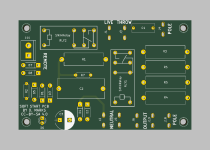
I chose this design (not mine, it's from D. Marks from Ampslab forum - see board pic) because it was part of a whole ecosystem power conditioner, soft-start, speaker protection and amp project. So I built the amp and soft-start, but didn't need in the previous amp when I changed it to an SMPS PSU, that amp previously used a +/-65Vdc 700VA with (4) 12,000uF 80V caps.
I'm open to another soft-start board BUT it has to offer 12V remote turn-on (I have a board for Mark Johnson's design, but don't believe it has remote turn-on), I am spoiled using a remote for my preamp and not turning on my amplifiers by hand.
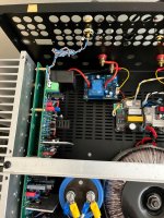
Included pics of my build, very modest compared to others on this thread, "might not look like much, but she sounds good and is dead quiet!" You can see the soft-start board, with a small 12V SMPS glued to the resistors for speaker protection.
It appears to be working and worked in 2 other amplifiers without the lights dimming. Testing with a DBT, the 150W bulb lights then dims and lights more brightly before going out over a 0.5 sec timeframe. The breaker doesn't trip or blow the mains fuse (I currently have 8A s/b mains fuse and 6.3A s/b rail fuses), however my lights dim considerably when I power it on. Looking at the schematic, would it help to replace the (4) 150r resistors with CL-60s in either parallel or series-parallel (since I have these on hand)? Or change the value of those 150r resistors, or a totally different modification?
I chose this design (not mine, it's from D. Marks from Ampslab forum - see board pic) because it was part of a whole ecosystem power conditioner, soft-start, speaker protection and amp project. So I built the amp and soft-start, but didn't need in the previous amp when I changed it to an SMPS PSU, that amp previously used a +/-65Vdc 700VA with (4) 12,000uF 80V caps.
I'm open to another soft-start board BUT it has to offer 12V remote turn-on (I have a board for Mark Johnson's design, but don't believe it has remote turn-on), I am spoiled using a remote for my preamp and not turning on my amplifiers by hand.
Included pics of my build, very modest compared to others on this thread, "might not look like much, but she sounds good and is dead quiet!" You can see the soft-start board, with a small 12V SMPS glued to the resistors for speaker protection.
Attachments


This afternoon I listened to the amplifier more comfortably. My speakers are old ... 4Ω /300W and connected to Nikos Dcg3 preamplifier (Salas). I play flac music with my friend Sonnya Mirand audio's dac 4490. The impressions are excellent in bass, detailed as well, with a large stereo image like something in 3D.
it's just that the amplifier breaks it hahahahaha it's a Greek expression.
Απλά φίλε μου Harry τα σπάει....
Many many thanks to the team .
it's just that the amplifier breaks it hahahahaha it's a Greek expression.
Απλά φίλε μου Harry τα σπάει....
Many many thanks to the team .
Great job Bullittstang.Is there a way to modify this soft-start schematic and offer a "slower" ramp-up soft-start? I have it hooked up to my Wolverine, running +/-70Vdc, with an 800VA toroidal and running (4) 33,000uF 80V "can" caps.
It appears to be working and worked in 2 other amplifiers without the lights dimming. Testing with a DBT, the 150W bulb lights then dims and lights more brightly before going out over a 0.5 sec timeframe. The breaker doesn't trip or blow the mains fuse (I currently have 8A s/b mains fuse and 6.3A s/b rail fuses), however my lights dim considerably when I power it on. Looking at the schematic, would it help to replace the (4) 150r resistors with CL-60s in either parallel or series-parallel (since I have these on hand)? Or change the value of those 150r resistors, or a totally different modification?
I chose this design (not mine, it's from D. Marks from Ampslab forum - see board pic) because it was part of a whole ecosystem power conditioner, soft-start, speaker protection and amp project. So I built the amp and soft-start, but didn't need in the previous amp when I changed it to an SMPS PSU, that amp previously used a +/-65Vdc 700VA with (4) 12,000uF 80V caps.
I'm open to another soft-start board BUT it has to offer 12V remote turn-on (I have a board for Mark Johnson's design, but don't believe it has remote turn-on), I am spoiled using a remote for my preamp and not turning on my amplifiers by hand.
Included pics of my build, very modest compared to others on this thread, "might not look like much, but she sounds good and is dead quiet!" You can see the soft-start board, with a small 12V SMPS glued to the resistors for speaker protection.
You can increase the RC time constant on the soft start but resistors which take the turn on thump often don't survive.
Might be worth exploring the CL60 option
Rick, Poseidon, Stuart, Dan, Anand-Check it like stated above. I have a Rigol bench supply and have to connect a red and a black from each channel to get a floating ground. My green lug connects to earth ground.
Thanks so much guys! The green center ground terminal on the power supply is earth ground and is not much help in this. You have to connect a wire from the black terminal of one side to the red terminal of the other side. You set the PS to Series Mode and the shunt is the floating ground and voila! The instruction manual was pretty vague so the "RTFM" principle does not apply here. Very grateful for the experienced help!
Jon
A question or two about an unconventional application.
I am currently building a couple of these (very slowly!) planned for use in a record cutting application where they will be driving a cutting head.
The power requirement for this is all about high frequency power, almost nothing is required at below 1kHz and very, very little is required at the typically 1.5kHz main cutter resonance, but at 18kHz the IRIAA and feedback have pushed the required power up by about 40dB!
Question is, what do people think about the sizing of the snubber resistor in the output stability network, this sort of abuse feels likely to result in considerable heating there, and will the thing slew fast enough to maintain full power out to 20kHz+? Basically the classic power spectrum of most audio is flattened or even reversed in this application.
A further question is how stable is the offset if deliberately dialled up to 100mV or so? My cutter thermal protection scheme uses a bridge circuit driven by a DC offset from the amplifier to measure the voice coil temperature and trip the system off if it ever exceeds 200c. Doing this does however require that the power amp maintains a set DC offset to bias the bridge. I am tempted to try a DC coupled variant with an external servo loop to control the DC level, but it would be simpler if the amp is well behaved to not bother.
There is about 26dB@1kHz of motional feedback (Really velocity feedback to deal with the cutters various infelicities) going to be wrapped around the amp, so little excess phase inside that loop is very much desired.
Thoughts?
What final output transistors did you use?Hi everyone... I've shared my build on the developers thread and it's time to put it out there for others to consider...
My intention from the outset was to build a quad amp to bi-amp my speakers. I began building Honey Badgers until I realized that my speakers are a particularly difficult load rated at 4 ohms, which was pretty concerning for me. So, I contacted Ostripper to see if there were any viable options and he told me that the Honey Badger wasn't up to the task and I really needed to move on to the Wolverine, which was in the design phase.
As a novice, the timing couldn't have been better. I was ready to build and when the time came for testing, I wanted to be part of it for the learning experience. Four test boards later... 2 literally worn out and in the trash and 2 still working and sitting on the shelf, the design and test team finally signed off on the design.
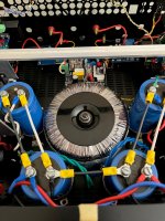
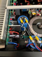
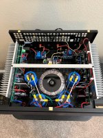
The months of testing allowed me to evaluate the physical layout of the amps in a 5U box, particularly with regard to the power supply. Mounting the boards perpendicular to the heat sink provided enough room for 2 boards and a speaker protection board on each side. The area in the middle of the chassis was going to have to accommodate the transformer, caps/rectifiers, soft start and a fan. I wasn't quite sure if a fan was going to be absolutely necessary, but I thought it would be a good idea to do it now rather than having to do it later.
I made an elevated chassis for the PSU to provide enough space underneath the transformer and cap board for the necessary peripherals. As well, I wanted to provide shielding for the transformer and other sources of noise. The attached photos show how this was arranged. which really worked out well. I was concerned about injecting noise with all the close proximity of everything, but the shielding did its job and testing revealed that it's quiet. Distortion testing revealed that the individual boards didn't lose any performance,
I've been using this setup for several months now and I've pushed it very hard to see if how hot it would get. As it turns out, I have yet to trigger the fan circuit. I have 40C thermostats and according to my temperature measurements the temperature is getting to just below the set point. My wife's set point is being exceeded much sooner... 😆
Nice build.
Scott
Stuart-
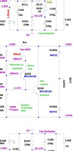
One IPS module seems to work OK. Can get up to 30-0-30V drawing only ~20 mA. The other module seems OK until I get up to ~10V per side then one leg of the PS snaps into constant current mode and reduces the voltage. Checked shorts, bridges, cold joints, misplaced caps, etc. Wondering if it is a semiconductor issue - perhaps one of the transistor pairs?
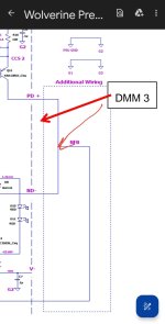
Tried tracing the voltages as shown on P 50 of the newest build guide. The exact location of the DMM3 test point is a little unclear (at least to me). Is it supposed to be the NFB<>PB+<>ND- shunt?
Thanks
Jon
One IPS module seems to work OK. Can get up to 30-0-30V drawing only ~20 mA. The other module seems OK until I get up to ~10V per side then one leg of the PS snaps into constant current mode and reduces the voltage. Checked shorts, bridges, cold joints, misplaced caps, etc. Wondering if it is a semiconductor issue - perhaps one of the transistor pairs?
Tried tracing the voltages as shown on P 50 of the newest build guide. The exact location of the DMM3 test point is a little unclear (at least to me). Is it supposed to be the NFB<>PB+<>ND- shunt?
Thanks
Jon
Hi Jon, it looks like that arrow moved for some reason. In this isolation test it is just emulating the output trace. Please see the correct location below.
You shouldn't have any issues with this test if everything is ok.
I suggest that you make a very close visual comparison between both boards checking all resistor values, component orientation etc.
If it checks out you may need to do a voltage comparison between the two boards. If you can you can connect them both at the same time. Then dial the voltage up to just below the point were your having the issue. Then take some comparison measurements using a common ground. This will help you quickly identify what voltages are correct and when are not. This will also help you identify the location were the problem exists. Please note there maybe more that one section were the voltages differs.
Good luck
Attachments
Update from post #2462 regarding the soft-start allowing too much current and dimming my lights.
Pulled the (4) 150r 5w resistors and replaced with two CL-60 thermistors in series to get ~20r cold resistance.
Worked like a charm, no more dimming lights and really not much heat either. Start out at ~80F and only maxed out at 100F, and cools down to 85F within a few seconds of the relay latching.
Q??? For D115, D116 "863-MBR1100G" is it OK to sub them with "637-SB1100"
https://www.mouser.com/datasheet/2/849/sb120-2577465.pdf
https://www.mouser.com/datasheet/2/849/sb120-2577465.pdf
I used these and they worked fine 750-SB1100E-G https://www.mouser.com/ProductDetail/750-SB1100E-G and there's 7k in stock now.
The ones I linked appear to have a higher peak current 30A vs. 10A.
Edit: read the datasheet wrong, yours are 40A vs. linked are 30A peak forward current. They should work fine.
The ones I linked appear to have a higher peak current 30A vs. 10A.
Edit: read the datasheet wrong, yours are 40A vs. linked are 30A peak forward current. They should work fine.
THX, wasn't sure how critical it is to the circuit.
The BOM makes me search due to discontinued or out of stock items!!! Ugh! But still fun and keeps me off the streets!
Scott
The BOM makes me search due to discontinued or out of stock items!!! Ugh! But still fun and keeps me off the streets!
Scott
Yes. You can also use sheet 2 of the BOM. As you may have seen, it has a list of AC transformer voltages and from that the expected DC voltages.For resistors in the IPS, just confirming the selection is based on max rail voltage?
I have reached the soldering stage so a few questions have appeared. The most important one relates to EF3-4 positioning of driver transistors Q107 and Q108. Originally these transistors have been placed on separate 3mm heatsinks but the latest recommendation is to mount these drivers on the main heatsink. As I prefer to keep pcbs at the right angle to the main heatsink (easy access to pcb trimpots, test points etc) a problem has appeared. If I place drivers Q107 and Q108 on the main heatsink then I have to wire them to the pcb. Can I do this as wires will not be very short? It's not a problem to wire a temperature sensing transistor but in this case length of wires may become sensitive. Or with the right angle pcb to heatsink configuration should I keep these drivers (Q107 & Q108) on their original separate 3mm heatsinks?
I understand that in EF3-3 these driver transistors (Q107 & Q108) remain on their separate 3mm heatsinks, am I right?
The other questions concern less sensitive issues, namely why high voltage transistors ksa992 were used for Q9 and Q10, which collector-emitter voltage is below 1.5V? I'd prefer to use here my 2sa1015 or ksa1015 transistors. By the way 2sa1015L or ksa1015 are also low noise (typ 0.2db at 1kHz, max 3dB) and have much better linearity than BC transistors used in LTP here.
I also have awg15 (1.5mm) wire and awg13 (1.8mm) wire. AWG13 is too thick but if I was to use awg15 wire how many turns on 12mm (or different diameter former) I need?
Instead of ksa1381/sc3503 I'll probably use 2sa1209s/sc2911s
I'll be grateful for all comments. Thank you.
cheers,
PS. I still have some "esoteric" low noise transistors such as 2sa970bl and 2sa1085, very linear but most likely I'll keep them for projects with high voltage LTPs.
If you are going perpendicular install with an EF3-4, you would need to use the Q107 and Q108 drivers on their own 75x50x3mm heatsink as long as your outputs aren't MT200's. You would no longer need the hole in said heatsink for Q103, as that has been reallocated to ambient duty and would require flywires to the main heatsink, as per post 2057, or flywires to the spare Q104 labelled position for main heatsink monitoring.
Last edited:
Yes. Please follow the size requirements as shown in the build guide.should I keep these drivers (Q107 & Q108) on their original separate 3mm heatsinks?
You might want to have a closer look at thatThe other questions concern less sensitive issues, namely why high voltage transistors ksa992 were used for Q9 and Q10, which collector-emitter voltage is below 1.5V? I'd prefer to use here my 2sa1015 or ksa1015 transistors. By the way 2sa1015L or ksa1015 are also low noise (typ 0.2db at 1kHz, max 3dB) and have much better linearity than BC transistors used in LTP here.
- Home
- Amplifiers
- Solid State
- DIY Class A/B Amp The "Wolverine" build thread