Which of them did you like the most? Playing well-recorded music with good/very good dynamic range.Measurements solely, do not tell how “good” an amplifier is. Listening is what will determine if you think the amplifier is a keeper or not.
The main problem is, you’ll need to build them all to listen for yourself 😊
How is everyone going with their Wolverine amplifier builds ?
I am working on another video for the Wolverine build series on YouTube in the background....
- Dan
I am working on another video for the Wolverine build series on YouTube in the background....
- Dan

Primarely enjoying the summer. Now and then sourcing parts.
After a long break from DIY-electronics I had to dust off old skills, and combatting new chalages. Found out I now need a magnifying glass for PCB-soldering!
I dont expect it to be ready before 2023.
After a long break from DIY-electronics I had to dust off old skills, and combatting new chalages. Found out I now need a magnifying glass for PCB-soldering!
I dont expect it to be ready before 2023.
I'm making some progress on my mono blocks. Waiting on speaker terminal connectors for the almost completed amp. Assembling the 2nd amp, passed initial tests with bench power supply, finishing the regular power supply to test further.


You are correct on both boards. I also added a seperate board not shown yet for adding current overload protect to the Bonsai board. Should trip at 7 amps across one output pair. So far I like the Mark Johnson Board, especially having an LED for on and for off. I used an RGB LED switch on the front that will be blue in stand by and red when on. I'm looking to figure out how to have the green come on when the Bonsai board trips.
I also modded the Bonsai board to run both opto-couplers in series on one set of FET's, will decrease the switching time. You can see the red wires grafted to the Bonsai board.
I ordered PCB's for the Mark Johnson circuit last Monday at JLCPCB. Will take a while till they arrive as I opted for slow pace delivery. The price however made me smile.
Might follow you with the Bonsai circuit. The no relay design makes sense imo.
Might follow you with the Bonsai circuit. The no relay design makes sense imo.
Hi everyone... I've shared my build on the developers thread and it's time to put it out there for others to consider...
My intention from the outset was to build a quad amp to bi-amp my speakers. I began building Honey Badgers until I realized that my speakers are a particularly difficult load rated at 4 ohms, which was pretty concerning for me. So, I contacted Ostripper to see if there were any viable options and he told me that the Honey Badger wasn't up to the task and I really needed to move on to the Wolverine, which was in the design phase.
As a novice, the timing couldn't have been better. I was ready to build and when the time came for testing, I wanted to be part of it for the learning experience. Four test boards later... 2 literally worn out and in the trash and 2 still working and sitting on the shelf, the design and test team finally signed off on the design.
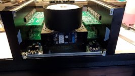
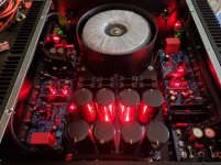
The months of testing allowed me to evaluate the physical layout of the amps in a 5U box, particularly with regard to the power supply. Mounting the boards perpendicular to the heat sink provided enough room for 2 boards and a speaker protection board on each side. The area in the middle of the chassis was going to have to accommodate the transformer, caps/rectifiers, soft start and a fan. I wasn't quite sure if a fan was going to be absolutely necessary, but I thought it would be a good idea to do it now rather than having to do it later.
I made an elevated chassis for the PSU to provide enough space underneath the transformer and cap board for the necessary peripherals. As well, I wanted to provide shielding for the transformer and other sources of noise. The attached photos show how this was arranged. which really worked out well. I was concerned about injecting noise with all the close proximity of everything, but the shielding did its job and testing revealed that it's quiet. Distortion testing revealed that the individual boards didn't lose any performance,
I've been using this setup for several months now and I've pushed it very hard to see if how hot it would get. As it turns out, I have yet to trigger the fan circuit. I have 40C thermostats and according to my temperature measurements the temperature is getting to just below the set point. My wife's set point is being exceeded much sooner... 😆
My intention from the outset was to build a quad amp to bi-amp my speakers. I began building Honey Badgers until I realized that my speakers are a particularly difficult load rated at 4 ohms, which was pretty concerning for me. So, I contacted Ostripper to see if there were any viable options and he told me that the Honey Badger wasn't up to the task and I really needed to move on to the Wolverine, which was in the design phase.
As a novice, the timing couldn't have been better. I was ready to build and when the time came for testing, I wanted to be part of it for the learning experience. Four test boards later... 2 literally worn out and in the trash and 2 still working and sitting on the shelf, the design and test team finally signed off on the design.
The months of testing allowed me to evaluate the physical layout of the amps in a 5U box, particularly with regard to the power supply. Mounting the boards perpendicular to the heat sink provided enough room for 2 boards and a speaker protection board on each side. The area in the middle of the chassis was going to have to accommodate the transformer, caps/rectifiers, soft start and a fan. I wasn't quite sure if a fan was going to be absolutely necessary, but I thought it would be a good idea to do it now rather than having to do it later.
I made an elevated chassis for the PSU to provide enough space underneath the transformer and cap board for the necessary peripherals. As well, I wanted to provide shielding for the transformer and other sources of noise. The attached photos show how this was arranged. which really worked out well. I was concerned about injecting noise with all the close proximity of everything, but the shielding did its job and testing revealed that it's quiet. Distortion testing revealed that the individual boards didn't lose any performance,
I've been using this setup for several months now and I've pushed it very hard to see if how hot it would get. As it turns out, I have yet to trigger the fan circuit. I have 40C thermostats and according to my temperature measurements the temperature is getting to just below the set point. My wife's set point is being exceeded much sooner... 😆
Attachments
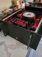
That is one hell of a build 😵. Looks amazing!! What size Transformer and voltage is it running?
I used Antek 1kva 40vac... The 57 volt rails provides adequate power. I was afraid of running out of room if I went larger...
Is your fan thermostat sensing ambient inside the enclosure or is it attached to the heat sinks? My heatsinks run about 39 degrees C at idle. I do have the EF3-4 boards running 71V.
My heat sinks are running about 37C at idle. The thermostats are mounted to the heat sinks... I tested the operation of the thermostats and as close as I could tell, they're closing at about 42C. I have additional shutdown thermostats mounted on a couple outputs as a contingency. They're set at 50C. At reasonable SPL's the sinks don't heat up as much as I anticipated. I have to push it to approach the fan setting.
Good to see builders posting there layouts, my builds on hold unfortunately but I can still garner ideas for a layout.
Fantastic build! 👏Hi everyone... I've shared my build on the developers thread and it's time to put it out there for others to consider...
My intention from the outset was to build a quad amp to bi-amp my speakers. I began building Honey Badgers until I realized that my speakers are a particularly difficult load rated at 4 ohms, which was pretty concerning for me. So, I contacted Ostripper to see if there were any viable options and he told me that the Honey Badger wasn't up to the task and I really needed to move on to the Wolverine, which was in the design phase.
As a novice, the timing couldn't have been better. I was ready to build and when the time came for testing, I wanted to be part of it for the learning experience. Four test boards later... 2 literally worn out and in the trash and 2 still working and sitting on the shelf, the design and test team finally signed off on the design.
The months of testing allowed me to evaluate the physical layout of the amps in a 5U box, particularly with regard to the power supply. Mounting the boards perpendicular to the heat sink provided enough room for 2 boards and a speaker protection board on each side. The area in the middle of the chassis was going to have to accommodate the transformer, caps/rectifiers, soft start and a fan. I wasn't quite sure if a fan was going to be absolutely necessary, but I thought it would be a good idea to do it now rather than having to do it later.
I made an elevated chassis for the PSU to provide enough space underneath the transformer and cap board for the necessary peripherals. As well, I wanted to provide shielding for the transformer and other sources of noise. The attached photos show how this was arranged. which really worked out well. I was concerned about injecting noise with all the close proximity of everything, but the shielding did its job and testing revealed that it's quiet. Distortion testing revealed that the individual boards didn't lose any performance,
I've been using this setup for several months now and I've pushed it very hard to see if how hot it would get. As it turns out, I have yet to trigger the fan circuit. I have 40C thermostats and according to my temperature measurements the temperature is getting to just below the set point. My wife's set point is being exceeded much sooner... 😆
My builds are the same, heatsinks warm to the touch after hours of reference level movies, I never measured them but they aren't much warmer then idle. I would guess around a 15 degree rise above ambient.
I simply fabricate them. The one in the photo is 85mm deep and 215mm in diameter. I use 18 ga. sheet metal and roll it to create the "can" and then weld it. The bottom is a 220mm x 220mm plate, which I then weld the can to. To finish it, I usually powder coat it, but paint works fine as well. Hope this helps...
- Home
- Amplifiers
- Solid State
- DIY Class A/B Amp The "Wolverine" build thread